Blister forming process comparison
Thermoforming and cold forming create blister cavities in different ways. Thermoforming heats a compatible polymer web before shaping it. Cold forming mechanically draws a laminated aluminium web without a heating stage for the forming material.
That difference affects material choice, cavity geometry, pack footprint, product visibility, tooling, inspection, machine configuration and the evidence needed for approval. It does not create a universal winner. The correct route is the one that supports the product’s approved container-closure requirements and can be controlled at the required output.

Decision boundary: material names alone do not establish shelf life, regulatory suitability or machine output. Use product-specific stability, compatibility and package evidence, then verify the proposed web and format on the intended equipment.
Quick comparison
Thermoforming and cold forming solve different packaging constraints
| Decision factor | Thermoforming | Cold forming |
|---|---|---|
| How the cavity is made | A thermoplastic web is heated to an approved forming condition and shaped in a tool. | A laminated aluminium web is mechanically drawn in a matched tool without heating the forming web. |
| Typical material families | PVC and approved coated or laminated thermoformable constructions; other polymers depend on the application and machine. | Approved aluminium-based cold-form laminates, paired with a compatible lidding construction. |
| Product visibility | Can be transparent when the selected construction is transparent. | Normally opaque, so product inspection and patient presentation need another approach. |
| Cavity design | Heating, draw ratio, thickness distribution, plug or pressure forming and cooling shape the usable cavity. | Laminate elongation, corner radii, draw direction, tool clearance and risk of mechanical damage shape the usable cavity. |
| Barrier evidence | Depends on the exact web construction, formed thickness, exposed area, seal and pack tests. | Depends on the exact laminate, formed condition, pinhole or damage control, seal and pack tests. |
| Machine scope | Requires the correct heating/forming system, web path, tooling and recipe. | Requires cold-form capability, matched tooling and web handling. Some configurable platforms process both routes; others do not. |
| Output and cost | Must be calculated from the approved card layout, index, process window, feeding, inspection and run conditions. | The same calculation applies, with cold-form material utilization and tooling constraints included. |
The table is a project map, not a specification. Supplier names such as PVC/PVDC or Alu-Alu describe broad families. Purchasing and validation documents must identify the exact construction, dimensions, direction, treatment or coating side, tolerances and test requirements.
Thermoforming process
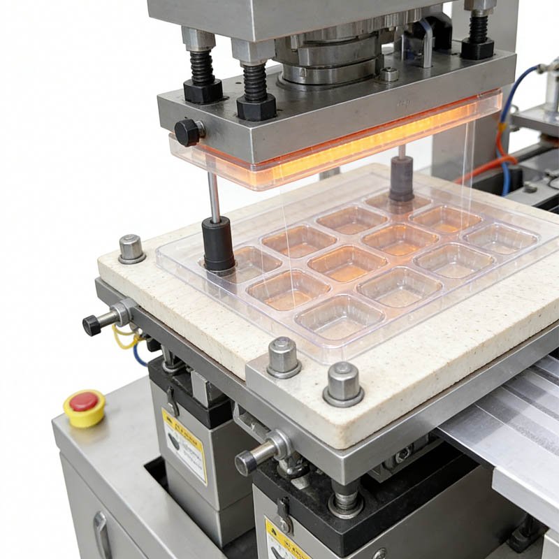
How a thermoformed blister cavity is created
The forming web is unwound, guided and brought to the forming station. The machine heats the web according to the approved material and process design. A pressure, vacuum, plug-assist or combined forming action then shapes the softened web into the cavity tool. Cooling helps the cavity retain its geometry before product loading.
What changes thermoforming quality
- material identity, construction, thickness, roll direction, storage and conditioning;
- heater design, measured web condition, forming time and the approved recipe;
- cavity depth, corner radius, wall angle, pitch and thickness distribution after forming;
- tool surface, vents, seals, plug condition, forming pressure or vacuum and cooling;
- web tension, edge guiding, index control and the condition after stops or restarts; and
- product loading, seal-land cleanliness, lidding compatibility and sealing conditions.
A transparent cavity can simplify some visual checks and lets a user see the product, but transparency is not proof of barrier performance or seal integrity. Conversely, a high-barrier thermoformable construction may meet a demanding product requirement when supported by the relevant data. The final decision comes from the proposed pack, not from a generic description of PVC.
Perlen Packaging’s pharmaceutical PVC information describes PVC as an established primary-packaging base and notes that it can be combined with PVdC across a range of barrier needs. This illustrates why “thermoforming” is not a single barrier level: the exact construction and test conditions matter.
Cold-form process
How a cold-formed aluminium cavity is created
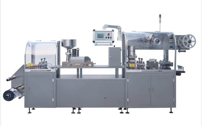
Cold forming uses a matched tool to mechanically draw an approved aluminium laminate into a pocket. The forming web does not pass through a heating stage for cavity formation. The laminate must move and elongate through the tool without unacceptable cracking, pinholes, delamination, wrinkles or loss of dimensional control.
What changes cold-form quality
- the full laminate structure, thickness tolerance, orientation and released material condition;
- cavity length, width, depth, corner radii, spacing and draw direction;
- matched-tool geometry, alignment, surface condition and web support;
- web tracking, tension, indexing and handling through later stations;
- inspection for local mechanical damage and the method used to qualify finished packs; and
- seal-land design, lidding compatibility, sealing process, perforation and cutting.
The opaque pack changes how filling is checked. A camera cannot inspect the product through the formed aluminium in the same way as through a clear cavity. The project may need inspection before lidding, a controlled reject-tracking method, X-ray or another justified system depending on the product and requirement. Do not leave this decision until after machine purchase.
Cold form often needs more planar web area for a given product because the cavity geometry must respect the laminate’s forming limits. That can change card count across the web, secondary-carton dimensions, material utilization and accepted output. Confirm the actual drawing rather than assuming the thermoformed layout transfers unchanged.
Barrier evidence
Compare finished-pack evidence, not isolated material claims
Water-vapour and oxygen transmission data can support material screening, but the values must identify the specimen and test conditions. Forming changes geometry and may change local thickness or create mechanical damage. The lidding and seal add other paths. The product experiences the complete container closure.
| Evidence | Useful question | Limit |
|---|---|---|
| Material specification | Which exact forming and lidding constructions are proposed? | Does not prove the formed pack or product shelf life. |
| Material transmission test | How does the applicable film or sheet transmit moisture under stated conditions? | Does not represent every cavity geometry, seal or defect. |
| Formed-cavity inspection | Did the process create the specified geometry without visible or measured damage? | Does not alone quantify long-term product protection. |
| Seal-strength or integrity test | Does the selected method show the specified seal or defect characteristic? | One method does not cover all package failure mechanisms. |
| Stability study | How does product quality change over time in the proposed container closure? | Must be translated into controlled pack and process specifications for routine production. |
ASTM F1249 covers determination of water-vapour transmission through applicable flexible barrier materials using stated test conditions. ASTM F88/F88M covers seal-strength measurement and failure mode for flexible barrier materials. Neither standard converts a flat-film result into a universal finished-blister shelf-life claim.
ICH Q1A(R2) connects stability evidence to temperature, humidity, light, shelf life and recommended storage conditions. Product owners should use their approved development and regulatory process to determine whether the proposed thermoformed or cold-formed pack supports the intended markets.
For distribution into hot or humid supply chains, also define the actual exposure route. The tropical-climate blister packaging guide separates room, warehouse, transport and market conditions.
Pack architecture
Design the cavity, seal land and card before comparing machines
A machine model cannot repair an undefined blister. Begin with the product dimensions and tolerances, orientation, feeding behaviour, dose count and protection needs. Create a controlled drawing that shows cavity geometry, pitch, seal land, perforation, opening features, artwork, coding area and final card dimensions.
Questions for both forming routes
- Is there sufficient clearance for product loading without movement that affects the seal land?
- Does the cavity protect the product from compression while avoiding unnecessary material and carton volume?
- Can the seal land remain clean and supported through sealing?
- Are perforation, cutting and opening forces compatible with the intended user and applicable requirements?
- Can print registration, coding, inspection and traceability fit the available web area?
- Does the card stack, collate and enter the secondary package reliably?
Thermoforming may allow a different cavity profile from cold forming for the same product. Recalculate the usable format area and packs per index for each candidate drawing. Comparing catalog cycles without this step can reverse the apparent output advantage after material utilization and card count are included.
The blister packaging materials guide provides a broader material map. Keep that material decision connected to the final drawing and validation evidence.
Equipment and tooling
Confirm whether one platform, two configurations or two machines are required
The old rule that one blister machine can never process both thermoforming and cold forming is too broad. Official machine portfolios show platforms that list both polymer and laminated aluminium forming materials, while other machines or purchased configurations support only one route. Capability depends on the machine architecture, installed stations, controls, web path, tooling and contract.
A dual-capability project may require different forming tools, heating or forming arrangements, web guides, feeder interfaces, recipes, inspection settings and change parts. Ask the supplier to identify what is standard, optional, exchanged or permanently installed. Define changeover steps, lifting and storage needs, line clearance, recipe control and checks before production restarts.
Uhlmann’s public blister-machine information lists thermoplastic and laminated aluminium materials on selected platforms and shows that forming depth and configuration can differ by material. This supports a project-specific capability check; it does not establish that every machine can switch between the two processes.
Output and operations
Calculate accepted packs instead of comparing maximum cycles
Commercial output depends on more than the cavity-forming method. Product feeding, packs per index, web utilization, sealing, print registration, inspection, reject tracking, stops, changeovers, cleaning and downstream cartoning all affect accepted finished packs.
- Freeze one candidate drawing for each route. Record card dimensions, cavities per card, cards per index and waste boundaries.
- Confirm the verified operating window. Use the actual product, forming and lidding materials, tooling and inspection scope.
- Define the scheduled run. Include start-up, sampling, planned stops, roll changes and the line interfaces covered by the test.
- Count accepted output. Record total cards, good cards, rejects, material waste, stops and operator interventions.
- Compare like with like. Use the same accepted-pack definition, run duration and boundary for both routes.
A faster nominal cycle can still deliver fewer accepted packs if the drawing fits fewer cards across the web or if feeding and inspection constrain the line. Use the blister-machine real-output calculation to build the comparison from the finished pack.
Ask for evidence at restart. Material near forming or sealing stations may experience a different process history during a stop. Define segregation, restart samples and the first acceptable output rather than testing only uninterrupted running.
Inspection and quality
Plan inspection around what the pack allows you to see
Inspection requirements begin with the defect and decision, not the camera. Define empty, missing, wrong, damaged or foreign-product conditions; web defects; seal-land contamination; code and artwork checks; registration; and the relationship between the detected web position and the rejected finished card.
A clear thermoformed cavity may support inspection after loading from one or more viewing directions. An opaque cold-form cavity can require inspection before lidding or a different sensing method. In both cases, product shape, colour, reflectivity, dust, web surface and line lighting affect the inspection design.

Challenge samples should be controlled and reconciled. The test must show that detection, tracking, physical rejection, reject confirmation and secure collection work across normal indexing, planned stops and restarts. A vision pass alone does not prove the correct finished card was removed.
21 CFR 211.130 requires written procedures designed to assure correct packaging and labelling materials, line clearance, inspection and control of operations. Translate those responsibilities into the URS, functional design, SOP and acceptance protocol rather than attaching a generic “GMP” label to either forming process.
Cost comparison
Build total cost from the approved pack and operating plan
It is unsafe to claim that one route is always cheaper. Material price, pack area, cavities per card, web waste, tooling, output, changeovers, labour, inspection, secondary packaging, storage and the cost of product-specific evidence vary by project and market.
| Cost input | Data required | Common comparison error |
|---|---|---|
| Forming and lidding webs | Quoted construction, width, thickness or mass, usable area, order quantity and waste basis. | Comparing price per roll without equal pack area or roll specification. |
| Pack layout | Approved cards per index, cavities per card, trim and registration allowance. | Using one layout for both forming methods when cavity geometry differs. |
| Machine and options | Quoted scope, tooling, feeders, inspection, coding, reject system and line interfaces. | Comparing base machines with different acceptance boundaries. |
| Changeover and cleaning | Measured labour, tools, material, line clearance and restart acceptance under the defined procedure. | Using an unsupported brochure time. |
| Accepted output | Good packs during the agreed run, plus rejects, stops and waste. | Using maximum cycles as saleable packs. |
| Development and lifecycle | Stability, compatibility, transport, qualification, change control and continuing verification work. | Treating machine purchase as the complete validation cost. |
The product-correct pack should be established before final cost comparison. If two routes both meet the required product and market evidence, compare their total cost on the same volume, service life, uptime basis and financial assumptions. If one route does not meet the approved requirement, its lower price is not an equivalent alternative.
Selection workflow
Use a gated decision instead of a rule of thumb
The decision may be different across a product portfolio. A flexible machine platform can be valuable when several approved packs require different materials, but only if its installed configuration, changeover controls and acceptance plan support those products. Do not buy flexibility that has not been defined or tested.
RFQ and FAT
Send enough evidence for a comparable supplier proposal
A useful RFQ identifies controlled inputs and open decisions. Ask every supplier to quote against the same scope so differences in machine, tooling, testing and documents remain visible.
- product dimensions, tolerances, presentation, handling risks and representative samples;
- approved or candidate forming and lidding specifications, roll data and conditioning instructions;
- controlled blister drawings for each forming route under review;
- target markets, required shelf life, labelled storage and the packaging evidence already available;
- finished accepted packs per hour or batch, run pattern and downstream demand;
- inspection, coding, data, rejection and reconciliation requirements;
- site utilities, room conditions, cleaning, access, lifting and material flow;
- changeovers, spare tooling, training, manuals and qualification-document scope; and
- FAT materials, run states, sampling, measurements, acceptance criteria and deviation handling.
During FAT, use the agreed product or justified substitute and the identified web constructions. Record settings, actual measurements required by the protocol, good output, rejects, waste, stops and interventions. A short sample that looks acceptable does not establish sustained output or product shelf life.
The blister machine URS guide can help organize the equipment boundary. Review broader process choices in the pharmaceutical blister packaging guide.
Primary references
Use each source for the question it covers
Questions from project teams
Thermoforming vs cold forming FAQ
What is the main difference between thermoforming and cold forming?
Thermoforming heats a compatible polymer web and shapes it in a forming tool. Cold forming mechanically draws an approved laminated aluminium web without heating the forming material. The difference affects materials, cavity geometry, visibility, tooling, inspection and machine configuration.
Is cold-form Alu-Alu always better than thermoforming?
No. Cold form and thermoforming address different product, pack and operating requirements. Choose from product-specific barrier, light, compatibility, stability, usability, inspection, output and cost evidence. A material family is not a universal quality ranking.
Can thermoformed blister packaging protect a moisture-sensitive product?
It may, if the exact thermoformable construction, formed geometry, lidding, seal and secondary pack support the required product evidence. Supplier material data can screen options, but the proposed container closure still requires the applicable pack and stability work.
Can one blister machine process both thermoforming and cold forming materials?
Some platforms can when they are configured with the required stations, web path, controls and tooling; others support only one forming route. Confirm the capability, conversion scope and acceptance tests in the supplier’s quotation and contract.
Why can a cold-form blister card be larger?
The aluminium laminate must be drawn within the approved material and tool limits. Required corner radii, spacing and cavity geometry can use more planar web area than a thermoformed cavity for the same product. Compare controlled drawings before calculating output.
Which process is faster, thermoforming or cold forming?
Do not decide from a generic cycle range. Accepted output depends on the machine configuration, card layout, cards per index, product feeding, forming and sealing window, inspection, rejects, stops and downstream equipment. Test both candidates on the same accepted-pack basis.
How should thermoforming and cold forming costs be compared?
Use quoted materials and pack area, approved layout, tooling and machine scope, accepted output, waste, changeovers, labour, inspection, secondary packaging and lifecycle evidence. Compare only routes that meet the product’s approved requirements.
What should be included in a thermoforming or cold-form FAT?
Define product and material identities, controlled drawing, tooling, recipe, run duration, start-up and restart states, inspection challenges, sampling, finished-pack tests, good output, rejects, waste, interventions, records, responsibilities and deviation handling.
Compare two controlled blister drawings before choosing the machine
Share your product, candidate materials, pack drawings, required accepted output, inspection scope and FAT expectations. HIJ can review the forming, sealing, tooling and line boundary against those inputs.
About this guide: prepared for packaging development, engineering, quality, regulatory, procurement and operations teams. It supports an evidence-based comparison and supplier discussion; it does not approve a material, container closure, process or product shelf life.