
HIJ-5050
End-of-Line Case Sealing Automation
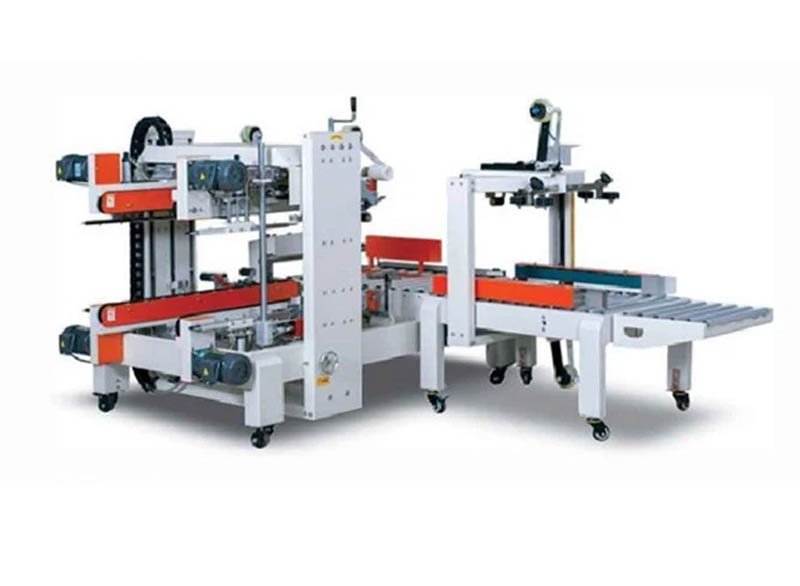
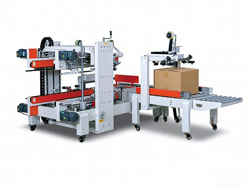
Fully Automatic Four Corner Sealing Machine for Unmanned Packaging Lines
HIJ-5050: seals all four corner edges of every carton automatically — creating a rigid, tamper-evident, dust-proof box at conveyor speeds of up to 20 m/min, with no operator at the sealing station.
20 m/min
Conveyor Sealing Speed
8 Edges
Sealed on Every Carton
24/7
Unmanned Operation
20+ Years Expertise
Global Shipping
CE-Marked Equipment
Quick Answer
What is a fully automatic four corner sealing machine?
A fully automatic four corner sealing machine is an end-of-line case sealer that applies adhesive tape to all four vertical corner edges of a carton — in addition to standard top-and-bottom sealing — producing a rigid, tamper-evident, dust-proof box without any operator. The HIJ-5050, built by HIJ Machinery (Wenzhou Trustar Machinery Technology Co., Ltd, est. 2004), seals cartons from 280 × 200 × 180 mm up to 700 × 500 × 500 mm at conveyor speeds of up to 20 m/min, using photoelectric detection for fully unmanned operation on automated packaging lines.
Key Takeaways
8-edge protection: tapes top, bottom, and all four corner edges — standard sealers leave corners exposed to dust, moisture, and tampering.
Truly unmanned: photoelectric detection auto-seals, alarms, and wakes — no operator required at the sealing station, 24/7.
20 m/min conveyor speed: actual cartons-per-hour depends on carton length — our engineers calculate exact throughput for your box size.
Tool-free size changeover: adjusts for carton length, width, and height in minutes, with tape widths of 48, 60, or 72 mm.
Tired of Inconsistent Sealing, High Labor Costs, and Packaging Bottlenecks?
If cartons leave your line with loose flaps, exposed corners, or crooked tape, the problem isn't your team — it's the sealing method.
Manual Taping Issues
Inconsistent seal quality, slow speeds, and recurring labor expenses at the end of your line — every shift, every day — directly impacting your unit cost and brand presentation.
Semi-Auto Limitations
A semi-automatic sealer still needs an operator to feed and align every carton, creating a bottleneck that caps the throughput of your otherwise automated packaging line.
Standard Sealer Gaps
Typical top-and-bottom case sealers leave all four corner edges open — a direct path for dust and moisture, and an easy target for in-transit tampering and pilferage.
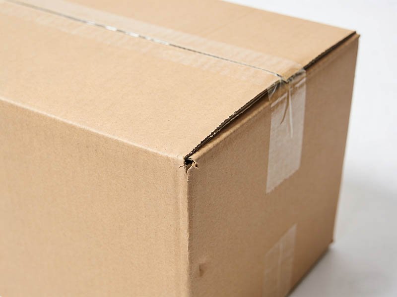
Standard Top/Bottom Sealing — corners exposed
HIJ-5050 Four-Corner Sealing — all 8 edges secured
The HIJ-5050 is engineered to eliminate all three problems at once. It removes the operator from the sealing station, standardizes seal quality on every carton, and closes the corner gaps that standard case sealers leave behind.
Engineering Highlights
Key Features of Our Automatic Box Corner Sealing Solution
Unmanned Automatic Operation
Advanced photoelectric detection automatically seals each carton, raises alarms on faults, and wakes from standby — integrating into your production line without human intervention.
Effortless & Quick Adjustment
Adjust for different carton sizes (length, width, height) without complex tools — minimizing downtime during batch changes and maximizing operational flexibility.
Rock-Solid, Reliable Structure
A reinforced steel frame and newly designed sealing head deliver stable, repeatable sealing results and a long service life — even in demanding 24/7 operations.
World-Class Electrical Components
Internationally recognized brands for all key electrical parts guarantee reliable performance, straightforward maintenance, and a reduced risk of unexpected failures.
Left & Right Drive System
Dual side-belt drive grips each carton firmly for smooth transport and precise corner taping — even on heavier boxes — with zero slippage or misalignment.
Enhanced Security & Protection
Four-corner sealing produces a tamper-evident, dust-resistant, moisture-resistant package — ideal for high-value goods in pharmaceutical, food, and electronics supply chains.
Technical Details
HIJ-5050 Four Corner Sealing Machine Specifications
Compare the HIJ-5050 four-corner sealer with a standard left/right-drive top-and-bottom case sealer to see exactly what you gain.
| Parameter | HIJ-5050 Four Corner Sealer | Standard L/R Drive Sealer |
|---|---|---|
| Sealing Method | Top + bottom + all 4 corner edges (8 edges) | Top + bottom only (2 edges) |
| Power Supply | AC 220V/380V, 50/60 Hz | 220V, 50 Hz |
| Working Air Pressure | 5.5–6 kg/cm² | N/A |
| Conveyor Sealing Speed | Up to 20 m/min | ≈ 1,000 cartons/hr |
| Min. Carton Size (L×W×H) | 280 × 200 × 180 mm | L (any) × W130 × H110 mm |
| Max. Carton Size (L×W×H) | 700 × 500 × 500 mm | L (any) × W500 × H500 mm |
| Applicable Tape Width | 48 / 60 / 72 mm | 36 / 48 / 60 mm |
| Table Height | 550–630 mm (adjustable) | N/A |
| Machine Dimensions (L×W×H) | 1955 × 1340 × 1330 mm | 1890 × 820 × 1410 mm |
| Operation Mode | Fully unmanned, photoelectric detection | Operator-assisted feeding |
Throughput in cartons per hour depends on carton length at a given conveyor speed — for example, shorter cartons yield higher CPH at the same 20 m/min line speed. Our engineers will calculate exact throughput for your carton dimensions.
The Process
How the Four Corner Sealing Machine Works
From infeed to fully sealed carton in one continuous, unmanned pass — here is the four-step working principle of the HIJ-5050.
1
Photoelectric Detection
The carton enters the infeed conveyor. Photoelectric sensors detect its presence and automatically wake the machine from standby — no operator input needed.
2
Centering & Grip
The left/right dual side-belt drive system centers and grips the carton firmly, ensuring stable, straight transport through the sealing station without slippage.
3
Corner Taping Cycle
Pneumatically actuated taping heads apply adhesive tape (48/60/72 mm) along all four vertical corner edges in a single automated cycle, reinforcing the carton structure.
4
Discharge & Next Carton
The fully sealed, tamper-evident carton discharges to the outfeed conveyor — ready for strapping, weighing, or palletizing — while the next carton enters continuously.
The Ideal Automated Sealing Solution for Demanding Industries
From pharmaceutical tamper evidence to e-commerce transit durability, the HIJ-5050 delivers the seal integrity that quality-driven operations demand.
Food & Beverage
Fully sealed corner edges help protect shelf-ready cases against dust and moisture ingress during storage and bulk shipment, supporting product integrity from your line to the distribution center.
Pharmaceutical & Daily Chemicals
Tamper-evident four-corner taping makes any in-transit opening immediately visible — a practical shipping-carton safeguard for regulated products. The machine is cGMP-ready and pairs with HIJ blister and cartoning lines.
E-commerce & Logistics
Corner-reinforced cartons resist compression and edge crushing far better than top/bottom-only taped boxes, helping reduce transit damage claims on long-distance and multi-touch shipping routes.
Electronics & Home Appliances
Superior dust and moisture protection for high-value electronic components and finished appliances, maintaining packaging quality — and theft deterrence — from factory to end user.
Seamlessly Integrates into Your Complete Packaging Line
The HIJ-5050 isn't just a standalone machine — it's a precision-engineered end-of-line component. We integrate it with case erectors and all-in-one packers, side-push case packers, and upstream cartoning machines to build a true unmanned packaging line — from product to sealed pallet-ready case.
Discuss Your Line Integration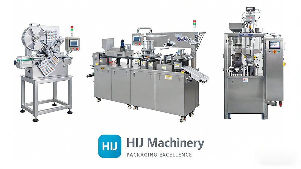

Forester Xiang
Founder & Chief Engineer · 20+ Years · 100+ Facility Audits in 30+ Countries
In more than 100 facility audits, one pattern keeps repeating: companies invest heavily in filling and cartoning precision, then lose it all at the last three meters of the line. A crushed corner or a lifted flap on the shipping case undoes everything the upstream machines did right — and the customer only ever sees the box.
That's why we engineered the HIJ-5050 around one principle: the shipping carton is part of your product. Sealing all eight edges isn't over-engineering; it's the difference between a case that survives a multi-touch export route and one that arrives looking like it was already opened. We don't just sell you a box sealer — we make sure the last machine on your line protects the work of every machine before it.
Turnkey Integration
We integrate the HIJ-5050 with your existing case erectors, packers, and palletizers — or design the complete turnkey packaging line around it.
FAT Before Shipping
We run Factory Acceptance Testing at our Rui'an facility using your own cartons, so performance is proven with your actual box sizes before the machine ships.
Lifetime Global Support
On-site installation, operator training, and 24/7 remote engineering support through our service & support program — maximizing uptime for the life of the machine.
About the Manufacturer
About HIJ Machinery & the HIJ-5050
The HIJ-5050 Fully Automatic Four Corner Sealing Machine is designed and manufactured by HIJ Machinery (legal name: Wenzhou Trustar Machinery Technology Co., Ltd), a packaging machinery manufacturer founded in 2004 and headquartered in Rui'an, Wenzhou, Zhejiang, China. HIJ Machinery produces case packing machines, cartoning machines, blister packing machines, capsule filling machines, and complete turnkey packaging lines for the pharmaceutical, food, cosmetic, and e-commerce industries.
All HIJ equipment is CE-marked and manufactured under the ISO 9001 quality management standard. Machines destined for pharmaceutical environments are built cGMP-ready; process validation (IQ/OQ/PQ) remains the customer's responsibility, and HIJ provides full documentation support. Technical oversight is led by Forester Xiang, Founder & Chief Engineer, with 20+ years of packaging machinery experience and 100+ facility audits across 30+ countries.
For specifications, integration studies, or a formal quotation for the HIJ-5050 four corner sealing machine, contact the HIJ engineering team — average response time is within 24 hours.
Expert Answers
Frequently Asked Questions about the Four Corner Sealing Machine
Instant answers to the questions our clients ask most about the HIJ-5050 and four-corner sealing technology.
What is a fully automatic four corner sealing machine?
A fully automatic four corner sealing machine is an end-of-line case sealer that applies adhesive tape to all four vertical corner edges of a carton, in addition to the top and bottom seams, without any operator. Using photoelectric detection, the HIJ-5050 automatically detects each carton, grips it with a left/right drive system, and tapes all four corners in one continuous pass — producing a rigid, tamper-evident, dust-proof box for unmanned packaging lines.
What is the main benefit of a four-corner sealer vs. a standard top-and-bottom sealer?
The primary benefit is total carton integrity. Standard case sealers tape only the top and bottom flaps, leaving all four corner edges open. The HIJ-5050 seals all eight edges of the carton, creating a rigid, tamper-evident box that is highly resistant to dust, moisture, and compression during transport — critical for long-distance shipping and high-value products in the pharmaceutical, electronics, and export food sectors.
How fast can the HIJ-5050 seal cartons?
The machine operates at a conveyor speed of up to 20 meters per minute. The actual cartons-per-hour rate depends on your carton length: shorter cartons yield a higher hourly count at the same line speed. Our engineering team calculates the exact throughput for your specific carton dimensions during the quoting process, so the figure you plan around is the figure you get.
What carton sizes can the four corner sealing machine handle?
The HIJ-5050 handles cartons from a minimum of 280 × 200 × 180 mm up to a maximum of 700 × 500 × 500 mm (L × W × H). Size changeover for length, width, and height is tool-free and takes only minutes, and the working table height is adjustable between 550 and 630 mm to match your existing conveyor line.
Is it difficult to change the tape rolls?
No. The tape heads are designed for quick roll changes, typically taking less than a minute for a trained operator. The machine uses standard adhesive tape rolls in 48 mm, 60 mm, or 72 mm widths, which are widely available worldwide. HIJ provides training videos and can arrange on-site training during installation so your team is fully confident with routine maintenance.
Can this machine be used as a standalone unit?
Yes. While the HIJ-5050 is designed for seamless integration into fully automated packaging lines with case erectors, case packers, and palletizers, it also works as a high-efficiency standalone sealing station. In standalone mode, an operator feeds closed cartons onto the infeed conveyor and the machine applies the four-corner taping automatically — a significant upgrade over manual taping even before full line automation.
How much does a fully automatic four corner sealing machine cost?
The final price of the HIJ-5050 depends on your carton size range, optional configurations (such as explosion-proof builds), and the level of line integration required. HIJ Machinery provides a formal, itemized quotation — including a complimentary ROI analysis based on your current sealing labor — within 24 hours of receiving your carton dimensions and line-speed requirements.
What is the lead time for this machine?
Standard HIJ-5050 models typically ship within 4–6 weeks from order confirmation and deposit. Customized solutions — special carton size ranges, explosion-proof configurations, or integration with existing line equipment — may require 8–10 weeks. Every machine completes Factory Acceptance Testing with your own cartons before shipping.
Still Have Questions?
Our packaging engineers are here to help. Get a free consultation and see how the HIJ-5050 fits your line.
Talk to Our Experts NowExplore More Case Packing Solutions
Build the complete end-of-line system — from case erecting and loading to sealing and turnkey integration.
Category Hub
Case Packing Machines
Compare all HIJ end-of-line case packing solutions — side-push, drop, wrap-around, and sealing systems — in one place.
View all machines → All-in-One SystemOpening, Loading & Sealing All-in-One Machine
Erect, load, and seal cases in one integrated machine — the natural upstream partner of the HIJ-5050.
See the machine → Case SealingAutomatic Case Sealing Machine (HIJ-600)
Standard top-and-bottom case sealer for lines where corner reinforcement is not required.
Compare sealers → Case PackingSide-Push Full Automatic Case Packing Machine
High-speed side-push case packer that feeds sealed-ready cases directly into the HIJ-5050.
See the machine → High ThroughputDouble Station Case Packing Machine
Dual-station case packing for higher-volume lines that demand maximum cartons per hour.
See the machine → Complete LinesTurnkey Packaging Line Solutions
From blister packing and cartoning to case packing, sealing, and palletizing — one integrated project, one partner.
Plan your line →
Take the Next Step
Get Your Free Turnkey Quote Today
Ready to Automate Your Carton Sealing Process?
Tell us your carton sizes and line-speed requirements. Our engineering team will provide a tailored quote and a complimentary ROI analysis based on your current sealing labor — within 24 hours.
Free Custom Quote
Complimentary ROI Analysis
No-Obligation Consultation
Your information is 100% secure. Average response time: within 24 hours.