
HIJ-600 Series

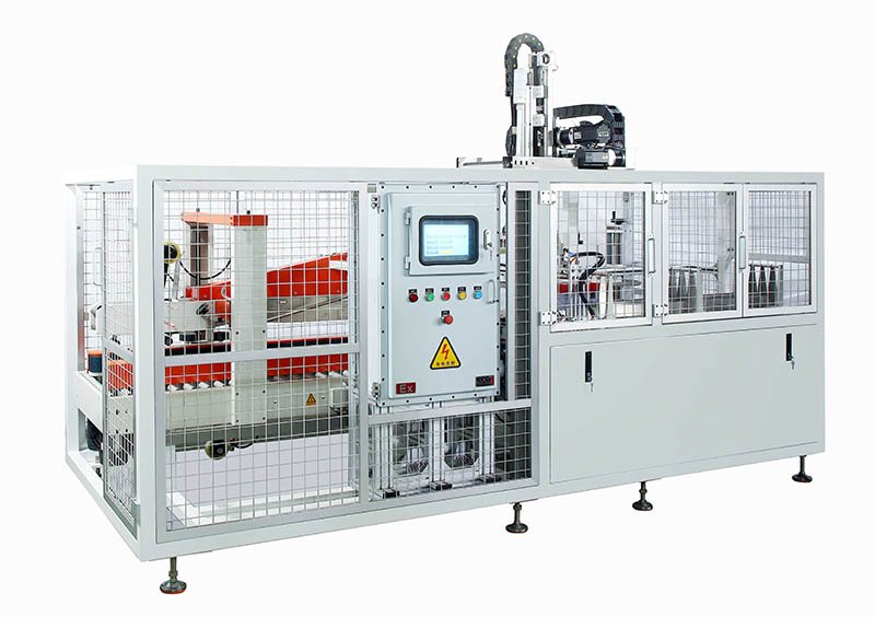


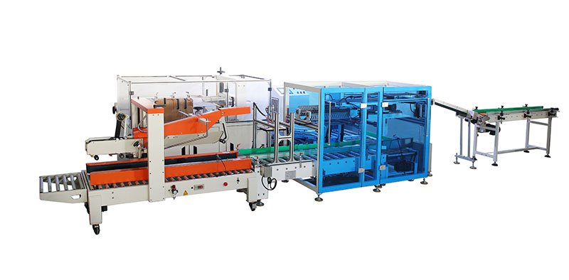
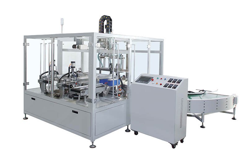
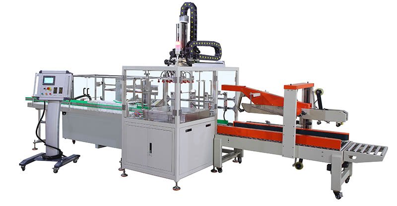
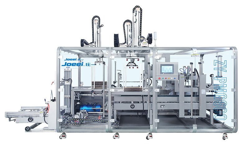
End-of-Line Packaging Equipment
Automatic Case Sealing Machine HIJ-600: Reliable, High-Speed Sealing for Your Production Line
Boost your packaging efficiency with our robust, top-and-bottom belt drive case sealer. The HIJ-600 delivers perfect seals on every box, every time.
Up to 720
Cases/Hour
Cases/Hour
Easy & Fast
Size Adjustment
Size Adjustment
Top & Bottom
Belt Drive
Belt Drive
Heavy-Duty
Industrial Build
Industrial Build
TRUSTED BY LEADING MANUFACTURERS WORLDWIDE
CE Certified
24/7 Global Support
20+ Years Experience
Quick Answer
What is an automatic case sealing machine?
An automatic case sealing machine (also called a carton sealer or case taper) applies pressure-sensitive tape to the top and bottom flaps of a filled corrugated carton in one continuous pass. The HIJ-600 automatic case sealer seals up to 720 boxes per hour using a top-and-bottom belt drive, handles cartons from 200–600 mm long, changes over between carton sizes in under one minute via hand-wheels, and runs on standard single-phase 220V power — replacing 2–3 manual taping operators at the end of a packaging line.
Key Takeaways
- Throughput: up to 720 boxes/hour — consistent, centered tape application on every carton, no operator fatigue.
- Carton range: L 200–600 mm × W 160–500 mm × H 200–600 mm, covering the vast majority of e-commerce and industrial shipping cartons.
- Drive system: top-and-bottom belt drive grips heavy or tall boxes far more securely than side-belt-only sealers.
- Changeover: hand-wheel width/height adjustment in under 1 minute — no tools, no skilled technician required.
- Tape compatibility: 48 mm, 60 mm and 72 mm pressure-sensitive tape (48/60 mm standard).
- Utilities: single-phase 220V 50Hz, compressed air 50 L/min — plugs into virtually any facility, mobile on 4 heavy-duty casters.
- Build standard: CE-marked, manufactured under ISO 9001, cGMP-ready design for pharmaceutical and food end-of-line packaging.
- Upgrade path: integrates directly with HIJ case packing machines for a fully automated erect–load–seal line.
Tired of Inconsistent Manual Taping and Production Bottlenecks?
Manual box sealing creates countless hidden costs and quality issues that drain your profitability. It's time for a better solution.
The Manual Sealing Reality
Every Day, Your Production Line Suffers From:
-
Painfully Low Efficiency Manual workers can seal only 15-20 boxes per hour, creating production bottlenecks that delay shipments and frustrate customers.
-
Inconsistent, Unprofessional Sealing Crooked tape, uneven coverage, and weak seals damage your brand image and lead to product damage during shipping.
-
Hidden Costs Everywhere Excessive tape waste, repetitive strain injuries, high labor turnover, and endless training cycles drain your budget.
-
Workforce Misallocation Your valuable employees waste time on repetitive, mind-numbing tasks instead of contributing to higher-value activities.
VS
The HIJ-600 Solution
Transform Your End-of-Line Packaging Process
-
36X Faster Production Seal up to 720 boxes per hour with consistent precision, eliminating bottlenecks and accelerating your entire operation.
-
Flawless, Professional Sealing Every box leaves your facility with perfectly centered, secure tape seals that protect products and enhance your brand reputation.
-
Rapid ROI & Cost Savings Reduce tape waste by 40%, eliminate labor costs, and see payback within 12-18 months through pure operational efficiency gains.
-
Empower Your Workforce Redeploy employees to quality control, customer service, or other value-adding roles while the HIJ-600 handles repetitive tasks.
THE BOTTOM LINE
This industrial case sealing equipment is the cornerstone of an efficient warehouse and packaging operation. Calculate Your SavingsWhy Choose the HIJ-600? Features That Drive Efficiency & ROI
Every component is engineered to maximize your packaging throughput while minimizing operational costs and downtime.
01
Precision Top & Bottom Belt Drive
Our top and bottom belt drive system grips cartons securely, ensuring smooth, stable transport without slipping or jamming, even for heavy or tall boxes. This results in perfectly centered, professional-looking tape application.
02
Fast & Easy Hand-Wheel Adjustment
Switching between different carton sizes is effortless. The intuitive hand-wheel controls allow your operators to make precise width and height adjustments in under a minute, minimizing downtime during production changeovers.
03
Heavy-Duty Construction for 24/7 Operation
Built with a robust steel frame and high-quality components, the HIJ-600 is engineered for durability and long-term reliability in demanding industrial environments. Invest in a machine that works as hard as you do.
04
User-Friendly Control Interface
Features a simple control screen for stand-alone debugging, production monitoring, and fault diagnostics. Includes output counting and safety functions like emergency stop and fault alarms for secure, worry-free operation.
Ready to Experience These Advanced Features?
Our team will help you evaluate how the HIJ-600's unique capabilities can optimize your specific packaging process and deliver measurable ROI.
Get Your Custom Solution QuoteHIJ-600 Technical Specifications
All the data you need for a seamless integration into your facility.
| Applicable Carton Range |
L: 200-600 mm
W: 160-500 mm
H: 200-600 mm
|
| Sealing Capacity |
Up to 720 boxes/hour (for common carton specifications) |
| Drive System | Top and Bottom Belt Drive |
| Tape Width |
48mm / 60mm / 72mm (Standard: 48mm & 60mm) |
| Power Supply | Single-phase 220V 50Hz |
| Air Source | 50 KG/CM²; 50 L/min |
| Machine Dimensions | L 1830 × W 835 × H 1640 mm |
| Machine Weight |
Approx. 250 KG (with 4 heavy-duty casters) |
Maximum Output
720
Boxes Per Hour
Footprint
Length
1830mm
Width
835mm
Height
1640mm
Compliance & Safety
CE Certified
ISO 9001:2015
cGMP Ready
Emergency Stop System
Need Detailed Engineering Documentation?
Get complete datasheets, CAD drawings, electrical schematics, and integration guidelines to evaluate the HIJ-600 for your specific application.
Global Applications
Versatile Sealing Solutions Across Industries
From food safety to pharmaceutical compliance, the HIJ-600 adapts to your industry's unique packaging demands with precision and reliability.
Food & Beverage
Securely seals boxes for snacks, drinks, and produce, ensuring product integrity and freshness during distribution. Meets food-grade hygiene standards.
E-commerce & Logistics
Ideal for high-volume fulfillment centers needing fast and reliable sealing for shipments. Handles diverse carton sizes with quick changeover.
Pharmaceuticals & Cosmetics
Provides clean, consistent sealing for regulated and high-value products. Supports cGMP compliance with detailed documentation and traceability.
General Manufacturing
A robust solution for any business shipping products in cartons, from electronics to hardware. Built to withstand demanding industrial environments.
Trusted by Industry Leaders Worldwide
Fortune 500 Manufacturers
Global Distribution Centers
cGMP Certified Facilities
Is the HIJ-600 Right for Your Industry?
Our packaging engineers have deep expertise across multiple sectors. Let us analyze your specific requirements and recommend the optimal sealing configuration.
Schedule an Industry-Specific ConsultationMore Than a Machine: A Partnership in Packaging Automation
Behind every HIJ machine is a commitment to your success, backed by two decades of industry expertise and a personal promise from our founder.

Forester Xiang
Founder & CEO | 20+ Years Industry Veteran
Turnkey Integration
We can integrate the HIJ-600 with case erectors, labelers, and palletizers to create a fully automatic packing line. No need to coordinate with multiple suppliers—we handle the entire system for you.
Global Support
Our engineers provide on-site installation, training, and 24/7 remote support to maximize your uptime. Wherever you are in the world, we're just a call away to keep your line running.
Parts & Consumables
We supply high-quality spare parts and tape to keep your box taping machine running smoothly. No more scrambling to find compatible parts from third parties—we've got you covered.
Experience the HIJ Partnership Difference
Let's discuss how we can optimize your packaging line with the HIJ-600 and our comprehensive support services. Your success is our success.
Start a Conversation with Our TeamManual Taping vs HIJ-600 vs All-in-One Case Packer
Where does an automatic case sealer fit in your end-of-line automation journey? Compare the three most common approaches side by side.
| Criteria | Manual Tape Gun | HIJ-600 Automatic Case Sealer | All-in-One Erect-Load-Seal Machine |
|---|---|---|---|
| Throughput | ~120–200 boxes/hour per worker, declining with fatigue | Up to 720 boxes/hour, constant all shift | Highest — continuous erecting, loading and sealing in one motion |
| Labor required | 2–3 dedicated taping operators | 1 operator loading cartons onto infeed | Near zero manual handling |
| Seal consistency | Varies by operator; skewed tape, wasted tape, weak seals | Perfectly centered tape on every box; top-and-bottom belt drive prevents skew | Fully consistent, machine-controlled |
| Changeover | None needed, but zero repeatability | Under 1 minute via hand-wheels | Recipe-based, longer setup, best for stable SKUs |
| Footprint & utilities | Workbench space | 1830 × 835 mm, single-phase 220V, mobile on casters | Full line footprint, three-phase power typical |
| Investment level | Lowest upfront, highest ongoing labor cost | Entry-level automation — typically pays back within the first year of saved labor | Highest capex, fastest ROI at high volume |
| Best for | Very low volume, irregular cartons | SMEs sealing 500+ boxes/day with 1–5 carton sizes | High-volume lines needing full automation |
Ready for full automation? See the opening, loading & sealing all-in-one machine or explore the complete case packing machine range.
Build Your Complete End-of-Line Packaging System
The HIJ-600 case sealer is one link in the chain. Pair it with upstream case packing and cartoning equipment for a fully automated production line.
All-in-One Case Erecting, Loading & Sealing Machine
Eliminate manual handling entirely — one machine opens cartons, loads products, and seals them in a single continuous motion.
View the all-in-one machineSide-Push Full Automatic Case Packing Machine
High-speed horizontal loading of bottles, cartons and pouches into shipping cases — the natural upstream partner of the HIJ-600.
Explore the side-push case packerDouble Station Case Packing Machine
Two loading stations working in parallel for double the case packing capacity without doubling the floor space.
See the double station packerFully Automatic Four Corner Sealing Machine
Reinforced corner sealing for heavy or export-grade cartons that need protection beyond a standard center seal.
Compare four-corner sealingCartoning Machines
Automatically fold cartons and insert blisters, bottles, tubes or sachets before they reach your case packing station.
Browse cartoning machinesTurnkey Packaging Line Solutions
From primary packaging to sealed shipping case — one supplier, one integrated line, one point of accountability.
Plan a turnkey line
Knowledge Center
Everything You Need to Know About Case Sealing
Eight engineering guides from the HIJ team — from working principle to price, selection, and troubleshooting. Written for procurement and production engineers, not marketers.
Basics
What Is a Case Sealing Machine? Types & How to Choose
The category primer: 4 machine types, how sealing works, and 6 B2B selection criteria.
Read the guide BasicsHow Does an Automatic Case Sealer Work?
The 5-stage sealing cycle, inside the taping head, and why the drive system is the spec that matters.
Read the guide BuyingCase Sealing Machine Price Guide 2026
Market prices by machine type, the 7 factors driving your quote, hidden landed costs, and ROI payback.
Read the guide BuyingSemi-Automatic vs Fully Automatic Case Sealer
8 decision criteria plus the volume-based rule that tells you which one your line actually needs.
Read the guide PlanningCase Sealer vs Case Erector vs Case Packer
The three end-of-line machines defined, the full erect–pack–seal sequence, and what to automate first.
Read the guide PlanningTape vs Hot Melt Glue for Case Sealing
8 procurement criteria and the four specific conditions where glue genuinely beats tape.
Read the guide BuyingHow to Choose a Case Sealing Machine: 12-Point Checklist
The complete procurement checklist — plus three supplier red flags that end the conversation.
Read the guide SupportCase Sealer Troubleshooting: 8 Problems & Fixes
Skewed tape, ragged cuts, jams and more — root causes, operator-level fixes, and a maintenance schedule.
Read the guideFrequently Asked Questions About the Automatic Case Sealing Machine
Straight answers from our engineering team on the HIJ-600 case sealer.
What is an automatic case sealing machine and how does it work?
An automatic case sealing machine applies pressure-sensitive tape to the top and bottom flaps of a filled carton in one pass. The operator pushes the filled box onto the infeed; the HIJ-600's top-and-bottom belt drive grips the carton, transports it through the sealing head, and applies perfectly centered tape to both flaps simultaneously at up to 720 boxes per hour. The sealed box exits ready for palletizing or shipping.
How do I adjust the machine for different carton sizes?
Use the clearly marked hand-wheels on both sides of the machine to set the new carton width and height. The entire changeover takes less than one minute, even for new operators — no tools or skilled technicians required. This makes the HIJ-600 ideal for lines running multiple carton sizes each day.
What carton sizes and weights can the HIJ-600 handle?
The HIJ-600 seals cartons from L 200–600 mm, W 160–500 mm, H 200–600 mm. Its robust steel frame and top-and-bottom belt drive are engineered for heavy, tall, or irregularly filled boxes that side-belt-only sealers struggle to grip, transporting them smoothly without slipping or skewed tape.
What type of sealing tape can be used?
The machine accepts standard pressure-sensitive tape in 48 mm, 60 mm and 72 mm widths (48 mm and 60 mm are the standard configuration). This includes common BOPP packing tape, printed branded tape, and reinforced tape for export cartons.
What utilities does the automatic case sealer require?
Only single-phase 220V 50Hz power and a compressed air supply of 50 L/min. With a compact 1830 × 835 × 1640 mm footprint, roughly 250 kg weight, and four heavy-duty casters, the HIJ-600 can be positioned — and repositioned — almost anywhere on your production floor.
What is the price and lead time for the HIJ-600 automatic case sealing machine?
Because the final configuration depends on your carton sizes, throughput target, and optional infeed/outfeed conveyors, the HIJ-600 is quoted per project. Most standard configurations ship within a short factory lead time, and every quote includes a detailed datasheet and layout drawing. Request a free quote and our team will respond within 24 hours with pricing, lead time, and a line-integration recommendation.
What is the difference between a case sealer and a case packer?
A case sealer like the HIJ-600 tapes the flaps of an already-filled carton. A case packer loads products into the carton first — see our side-push automatic case packing machine. Combined systems such as the all-in-one erect-load-seal machine perform both steps plus carton erecting in a single unit.
Do you offer installation, training, and after-sales support?
Yes. Every HIJ-600 ships with detailed installation documentation and video guidance, and our engineers provide remote commissioning support and operator training. Spare parts and lifetime technical support are covered under our service & support program, with on-site service available for turnkey line projects.
Still Have Questions About Case Sealing Automation?
Send us your carton dimensions and daily output — we'll recommend the right configuration and send a formal quotation within 24 hours.
Get Free Turnkey QuoteAbout HIJ Machinery & This Page
HIJ Machinery (legal name: Wenzhou Trustar Machinery Technology Co., Ltd) is a pharmaceutical, cosmetic, and food packaging machinery manufacturer founded in 2004 in Rui'an, Wenzhou, Zhejiang, China. The company designs and builds blister packing machines, cartoning machines, capsule filling machines, cosmetic filling lines, and end-of-line case packing machines — including the HIJ-600 automatic case sealing machine featured on this page. Equipment is CE-marked, manufactured under the ISO 9001 standard, and built cGMP-ready, and has been exported to more than 30 countries.
This page was written and technically reviewed by Forester Xiang, founder and chief engineer of HIJ Machinery, drawing on 20+ years of packaging engineering experience and more than 100 pharmaceutical facility audits worldwide. Learn more about HIJ Machinery, our quality philosophy, or contact our engineering team directly.