
HIJ-GZB200 · Pharmaceutical-Grade Aseptic Equipment
Double-Head Prefilled Syringe Vacuum Filling & Plugging Machine
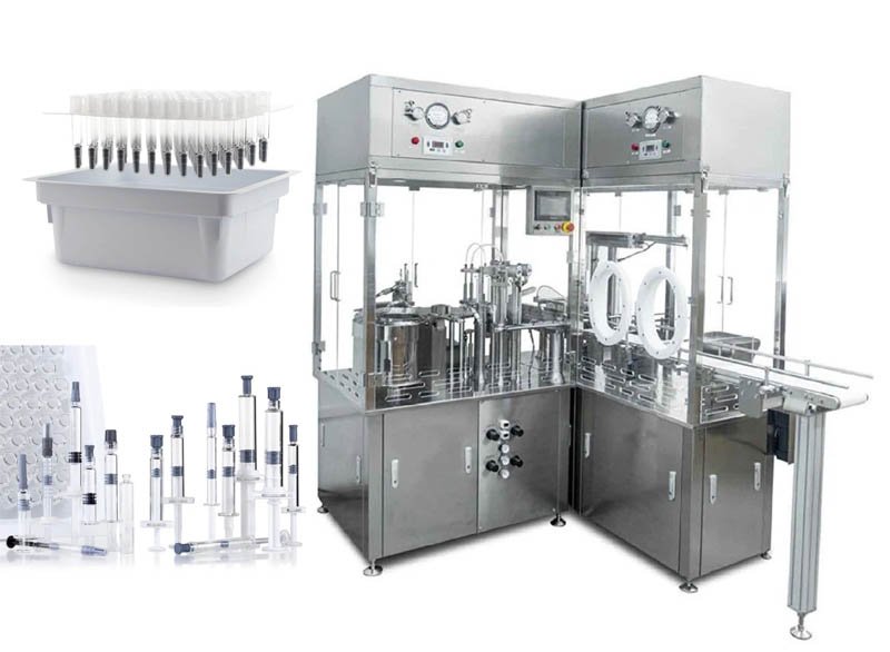
The HIJ-GZB200 delivers bubble-free vacuum filling and particle-free vacuum stoppering for viscous injectables like hyaluronic acid on BD, BG & SCHOTT nest-based SCF syringes — with ±1–2% dosing accuracy and 800–1,200 syringes/hour output. cGMP-ready design engineered for aseptic prefilled-syringe production.
cGMP-Ready & CE-Marked Design
FAT / SAT / IQ-OQ-PQ Support
Global Installation & Service

What is a double-head prefilled syringe vacuum filling machine?
A double-head prefilled syringe vacuum filling machine is aseptic pharmaceutical equipment that fills and stoppers nest-based SCF syringes under vacuum. Two servo ceramic-plunger heads dose viscous injectables bubble-free, while vacuum stoppering seats rubber plugs particle-free. The HIJ-GZB200 runs 800–1,200 syringes/hour at ±1–2% accuracy.
Key Takeaways
Bubble-free vacuum filling ideal for viscous products like hyaluronic acid, biologics and dermal fillers.
Vacuum stoppering eliminates friction particles, protecting particulate-matter test results.
800–1,200 syringes/hour with two servo-driven ceramic plunger heads at ±1–2% accuracy.
Handles 0.5 / 2.25 / 10 / 20 ml BD, BG & SCHOTT nest syringes (tooling change per size).
AISI 316L contact parts, cGMP-ready design, optional Class-100 laminar-flow hood.
Chinese manufacturing economics with IQ/OQ/PQ documentation support for your validation.
See It In Action
HIJ-GZB200 Vacuum Filling & Stoppering — Live Process
Watch the HIJ-GZB200 run a full cycle: automatic nest de-lidding, dual-head ceramic-plunger vacuum filling, and integrated vacuum stoppering — engineered to keep viscous injectables bubble-free and particle-free.
Play
Dual-Head Vacuum Filling
Aseptic Vacuum Stoppering
Servo-Driven Precision
Critical Production Challenges
Are Air Bubbles, Particle Contamination and Dosing Drift Compromising Your Injectables?
Air Bubbles & Oxidation
Conventional atmospheric filling traps air in viscous products like hyaluronic acid and biologics, driving oxidation and inaccurate delivered dose. The GZB200's vacuum filling removes trapped air before stoppering.
Particulate Contamination
Friction during rubber-plug insertion sheds micro-particles that fail particulate-matter testing and trigger recalls. Vacuum stoppering seats the plug without vibration friction, protecting your test results.
Incomplete Filling & Voids
High-viscosity materials leave voids and air pockets that ruin fill-volume uniformity. Vacuum-assisted, liquid-level-rising needle filling ensures the dose body fills completely, fault-free.
Aseptic Workflow Visualized
The HIJ-GZB200 Six-Stage Vacuum Filling & Plugging Process
A fully automated, servo-controlled workflow engineered to minimize operator intervention in the sterile zone and guarantee bubble-free, particle-free prefilled syringes.
01Step 01
Automatic Loading & De-lidding
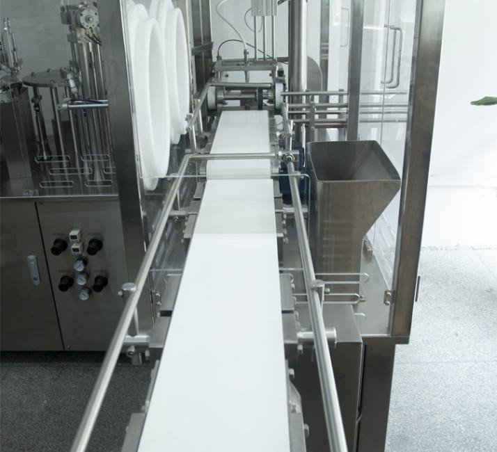
Operators simply remove the sealing film from the tub; the machine de-lids the nest and loads syringes onto the conveyor, minimizing human contact in the aseptic zone.
02Step 02
Syringe Comb & Slide-In
Nested syringes are indexed on the comb plate together with the tub liner and fed automatically into the turntable for precise station positioning.
03Step 03
Dual-Head Vacuum Filling
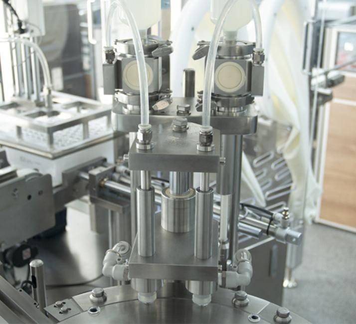
Two servo-driven ceramic plunger pumps dose liquid with the fill needle rising up the barrel to prevent splashing. Vacuum removes trapped air for bubble-free, high-accuracy fills.
04Step 04
Automatic Plug Feeding
A stainless vibratory bowl arranges rubber plugs and transports them to the placement position, custom-tooled to your specific plug geometry.
05Step 05
Vacuum Stoppering
The stopper rod integrates with a vacuum body: the syringe is pressed and evacuated, then the plug is seated to the exact liquid level — friction-free, particle-free, headspace-controlled.
06Step 06
Automatic Discharge
Finished, stoppered syringes are discharged automatically, ready for downstream labeling, blistering or cartoning line integration.
Complete Technical Data
HIJ-GZB200 Specifications
Contact parts in AISI 316L stainless steel and medical-grade silicone; main body in AISI 304 — engineered for cleanability, durability and cGMP-ready aseptic operation.
| Parameter | Specification |
|---|---|
| Model | HIJ-GZB200 |
| Applicable Materials | Liquid and ointment (including viscous products) |
| Applicable Syringe Specifications | 0.5 ml, 2.25 ml, 10 ml, 20 ml (not universal; tooling change per size) |
| Filling Accuracy | ±1–2% |
| Number of Filling Needles | 2 needles (double-head design) |
| Production Capacity | 800–1,200 syringes/hour |
| Vacuum System | 6×10⁻² Pa, 20 L/S |
| Filling Pump | Ceramic plunger pump (acid/alkali & wear resistant) |
| Control System | Siemens PLC + HMI, servo-driven synchronous actions, real-time fault alarm |
| Compressed Air | 0.55–0.75 MPa, 15 L/S |
| Total Power | 3 KW |
| Voltage | 380V / 220V, 50–60 Hz |
| Machine Dimensions | L 1020 mm × W 840 mm × H 1730 mm |
| Equipment Weight | 400 KG |
| Contact Materials | AISI 316L stainless steel + medical silicone rubber |
| Options | Class-100 laminar-flow hood (CLZ-1); automatic feeding system with heating & stirring |
Wide SCF Syringe Compatibility
Designed for SCF nest-based prefilled syringes from BD, BG, SCHOTT and major domestic manufacturers, with other syringe types available on a customized basis. Format changes between 0.5 / 2.25 / 10 / 20 ml sizes are handled via tooling; large fill-volume differences may require a filling-pump swap.
Need a customized configuration or the full datasheet?
Tell us your syringe size, product viscosity and target output — we'll spec the right GZB200 build for you.
Transparent Pricing
HIJ-GZB200 Price (FOB)
We publish an honest starting price so you can budget with confidence. Final FOB pricing depends on syringe format, laminar-flow-hood and auto-feed options, and validation-documentation scope.
Starting From (FOB Ningbo/Shanghai)
USD $XX,XXX
Configuration-dependent · Full IQ/OQ/PQ documentation available
Forester's Insight
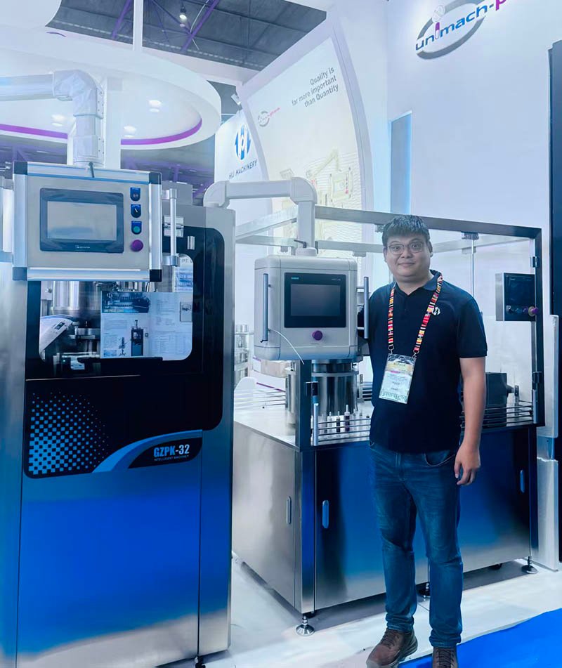
"The single most expensive mistake I see with prefilled syringes isn't the fill — it's the stoppering. Teams solve bubbles but then shed particles seating the plug, and a whole batch fails particulate testing. That's exactly why the GZB200 integrates the vacuum body into the stopper rod: it evacuates and seats the plug in one motion, so you don't trade one failure mode for another. Every feature here exists because I've watched a customer struggle without it."
Forester Xiang
Founder & Chief Engineer, HIJ Machinery · 20+ years, 100+ facility audits across 30+ countries
The HIJ Difference
Beyond the Machine: Your Partner in Aseptic Filling
We don't just sell equipment — we bring two decades of aseptic-filling problem-solving to every project, so your investment delivers from day one.
Deep Process Understanding
Ceramic-plunger, vacuum-fill and vacuum-stopper know-how tuned for viscous injectables — not generic liquid filling.
Smart Pricing
Chinese manufacturing economics with internationally sourced Siemens, Schneider, Panasonic and AIRTAC components.
Validation Support
FAT/SAT plus DQ/IQ/OQ/PQ documentation to support your in-house qualification and regulatory submissions.
Global Rapid Service
Remote diagnostics and on-site installation across 30+ countries, with spare-parts and tooling support.
Manufacturer & Product Facts
HIJ-GZB200 Entity Reference
Product Entity
- Product
- Double-Head Prefilled Syringe Vacuum Filling & Plugging Machine
- Model
- HIJ-GZB200
- Category
- Aseptic prefilled-syringe (SCF) filling equipment
- Output
- 800–1,200 syringes/hour
- Accuracy
- ±1–2%
- Formats
- 0.5 / 2.25 / 10 / 20 ml
- Key Tech
- Dual ceramic-plunger vacuum filling + vacuum stoppering
Manufacturer Entity
- Brand
- HIJ Machinery
- Legal Name
- Wenzhou Trustar Machinery Technology Co., Ltd
- Founded
- 2004
- HQ
- Rui'an, Wenzhou, Zhejiang, China
- Founder
- Forester Xiang, Chief Engineer
- Expertise
- 20+ years, 100+ facility audits, 30+ countries
- Standards
- cGMP-ready design, CE-marked, ISO 9001 manufacturing
About this machine: The HIJ-GZB200 is a double-head, servo-driven prefilled-syringe vacuum filling and plugging machine manufactured by HIJ Machinery (Wenzhou Trustar Machinery Technology Co., Ltd). It fills viscous injectables such as hyaluronic acid, dermal fillers and biologics bubble-free using two ceramic plunger pumps under vacuum, then seats rubber plugs particle-free via an integrated vacuum-stopper body. Built with AISI 316L contact parts and a cGMP-ready design, it processes BD, BG and SCHOTT SCF nest syringes at 800–1,200 units/hour with ±1–2% accuracy, and supports customer IQ/OQ/PQ validation with full documentation.
Technical Answers
Frequently Asked Questions
Expert answers to the questions pharmaceutical engineers ask most about vacuum syringe filling and stoppering.
How does the GZB200 handle high-viscosity products like hyaluronic acid?
The HIJ-GZB200 uses ceramic plunger pumps that resist wear and scoring from abrasive, viscous media, combined with a vacuum filling system that pulls trapped air out so the syringe body fills completely without bubbles or voids. The fill needle rises up the barrel as it doses to prevent splashing, which is essential for accurate delivery of hyaluronic acid, dermal fillers and biologics.
What is vacuum stoppering and why does it matter?
Vacuum stoppering seats the rubber plug while the syringe is under vacuum, so the plug contacts the liquid surface with controlled headspace and without vibration friction. This avoids the micro-particles that friction-based plunger insertion generates — a leading cause of failed particulate-matter tests. On the GZB200 the stopper rod and vacuum body are integrated into a single station.
Which syringe sizes and brands does it support?
The GZB200 is designed for SCF nest-based prefilled syringes from BD, BG and SCHOTT and major domestic makers, in 0.5, 2.25, 10 and 20 ml formats. Sizes are not universal — a tooling change is required between formats, and large fill-volume differences may require a filling-pump swap. Other syringe types can be accommodated on a customized basis.
What output and accuracy can I expect?
Rated capacity is 800–1,200 syringes per hour with two servo-driven filling needles, at a filling accuracy of ±1–2%. Actual throughput depends on syringe size, product viscosity and dose volume.
Is the machine cGMP-ready, and do you support validation?
Yes. Contact parts are AISI 316L stainless steel with medical silicone; the body is AISI 304, with no sanitary dead corners — a cGMP-ready, CE-marked design built to ISO 9001 manufacturing standards. We provide FAT/SAT and DQ/IQ/OQ/PQ documentation to support your own qualification and regulatory validation. Certification of the finished process remains the customer's responsibility.
Can it run in a cleanroom, isolator or under laminar flow?
The GZB200 offers an optional Class-100 (hundred-level) laminar-flow hood for high-cleanliness production and can be integrated into your cleanroom layout. Its modular design allows stand-alone operation or in-line connection to downstream equipment. Discuss your RABS/isolator requirements with our engineers for a tailored configuration.
How is the syringe loaded — how automated is it?
Operators manually remove the tub sealing film; the machine then automatically de-lids the nest and loads syringes onto the conveyor and turntable, minimizing human intervention in the sterile zone. An optional automatic feeding system with heating and stirring is available for viscous materials with level sensing.
What is the lead time and installation process?
Lead time depends on configuration and tooling; we confirm a schedule with your order. Every machine ships after Factory Acceptance Testing (FAT), and we support Site Acceptance Testing (SAT) and on-site installation and commissioning, with remote diagnostics and spare-parts support across 30+ countries.
Have more questions about your aseptic filling project?
Our engineers will review your product, syringe format and output targets — free of charge.
Ask Our EngineersExplore the Prefilled Syringe Range
Compare Machines & Plan Your Line
Syringe Filling Machines
Prefilled Syringe Filling — Hub Single-Head Vacuum Filling Machine Double-Head Plastic Syringe Filler Prefilled Plastic Syringe FillerDownstream Packaging
Prefilled Syringe Blister Packing Syringe Blister Packing Machine Blister Cartoning MachineReady to Spec Your Prefilled Syringe Line?
Get a tailored HIJ-GZB200 proposal — syringe format, vacuum configuration, laminar-flow options and full validation documentation, priced transparently.
Get Free Turnkey Quote