
ISO 9001
Certified
ISO 9001 | CE Certified



Liquid Packaging Solution
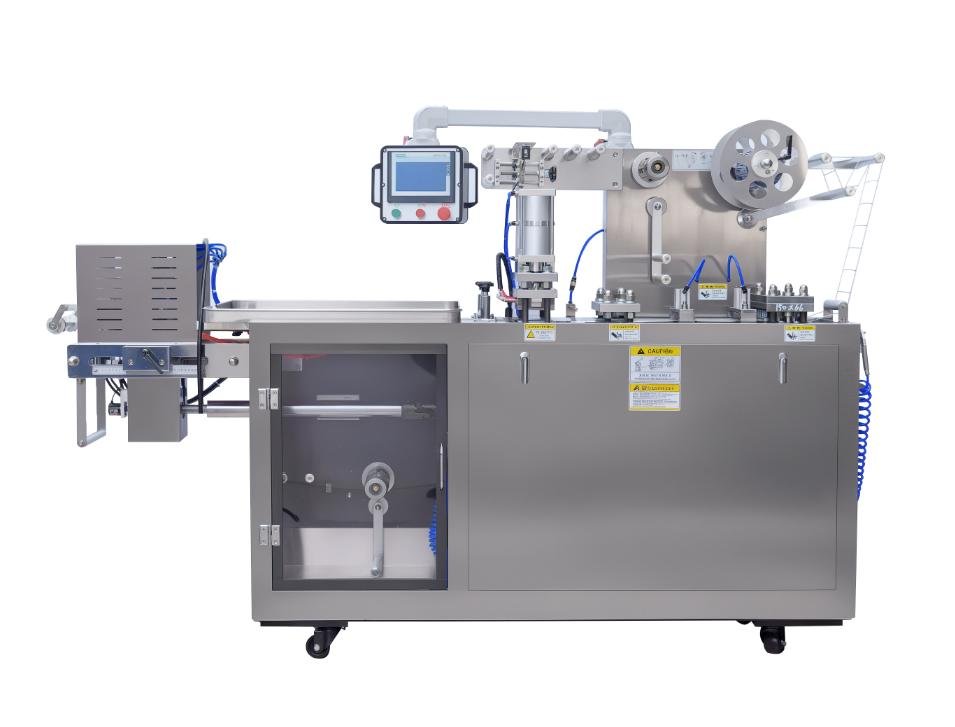
Liquid Blister Packaging Machine
Liquid Blister Packaging Machine
Professional Solution for Liquid & Semi-Liquid Products
Precision-engineered liquid blister packing system designed for honey, jam, sauce, cosmetics, and pharmaceutical liquids. Featuring 316 stainless steel construction, precise dosing, and zero-leakage sealing technology.
20 Years Experience
100+ Global Clients
30-45 Days Delivery
- 316SS Liquid Feeding System: Interlayer heating for viscous liquids, removable piston for easy cleaning
- Precision Filling: ±0.1ml accuracy, suitable for 0.5ml-50ml volume range
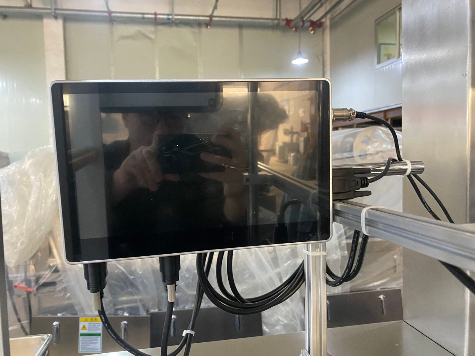
- Japanese Mitsubishi PLC: Servo control system, low failure rate, intuitive HMI operation
- GMP Compliant Design: Full documentation (IQ/OQ) provided, FDA/EU material standards
⚡ Quick Facts
HIJ Liquid Blister Packaging Machine — Verified Specifications
HIJ liquid blister packaging machines are specialized forming-filling-sealing systems manufactured in Wenzhou, China. Operating at 35 cycles per minute, HIJ machines fill liquids from 0.5ml to 30ml per cavity with ±1% accuracy, processing viscosities from 5cP (water-thin) to 100,000cP+ (paste).
Production Speed
35 cycles/min (≈400 cavities/min)
Fill Volume Range
0.5ml – 30ml per cavity
Viscosity Capability
5cP – 100,000cP+ (water to paste)
Forming Area
130 × 100 mm
Compliance
cGMP / 21 CFR Part 11 / CE / ISO 9001
Lead Time
12–16 weeks (FOB Wenzhou)
Markets Served
60+ countries worldwide
Manufacturer
HIJ Machinery (Wenzhou), China
📧 [email protected] | 💬 WhatsApp: +86 13868822120
Get Custom Quote →
Industry Knowledge Base
What is a Liquid Blister Packaging Machine?
Understanding the specialized technology designed for liquid and semi-liquid product packaging
Definition
A Liquid Blister Packaging Machine is a specialized pharmaceutical and food-grade packaging equipment designed to precisely dose, seal, and protect liquid or semi-liquid products in individual aluminum-plastic or aluminum-aluminum blister cavities. Unlike conventional solid blister machines, liquid blister packers feature a precision filling system (typically using 316 stainless steel piston pumps), temperature-controlled forming zones, and hermetic sealing technology to prevent leakage and contamination.
This machine is essential for packaging products like honey portions, pharmaceutical oral liquids, cosmetic serums, condiment sachets, and industrial lubricants where dosing accuracy (±0.1ml), sterility, and extended shelf life are critical requirements.
Liquid Compatible
0.5ml - 50ml range
High Precision
±0.1ml accuracy
Zero Leakage
Hermetic sealing
How Does It Work? The 8-Step Process
- Film Unwinding: PVC or PET base film is unwound and pre-heated to optimal forming temperature (typically 130-160°C)
- Thermoforming: Vacuum or compressed air forms blister cavities in precise shapes and volumes
- Cooling: Formed blisters are cooled to prevent product degradation during filling
- Precision Filling: 316SS piston pump doses exact liquid volume into each cavity (±0.1ml tolerance)
- Lid Film Application: Aluminum foil or dialysis paper is applied over filled cavities
- Heat Sealing: Controlled temperature (150-190°C) and pressure create hermetic seal
- Batch Coding: Inkjet or thermal printer adds date, lot number, expiry information
- Die Cutting: Individual or strip blisters are cut to final size
Play
Watch: HIJ Liquid Blister Machine Operating at 35 cycles/min
Liquid vs. Solid Blister Packaging: Key Differences
While both machines use thermoforming and heat sealing, liquid blister packers require specialized components to handle the unique challenges of liquid products:
| Feature | Liquid Blister Machine | Solid Blister Machine |
|---|---|---|
| Filling System | 316SS piston pump with heating jacket | Vibration or vacuum feeder |
| Filling Accuracy | ±0.1ml (High precision) | ±1 piece (counting accuracy) |
| Sealing Requirement | Hermetic (100% leakage-free) | Standard seal (moisture barrier) |
| Material Compatibility | High-barrier films (PVDC, cold-form aluminum) | Standard PVC/Aluminum |
| Cleaning Frequency | Daily (GMP requirement) | Weekly or per batch |
| Temperature Control | Critical (±1°C precision) | Standard |
| Typical Products | Liquids, gels, pastes, creams | Tablets, capsules, pills |
Which Products Benefit from Liquid Blister Packaging?
Food Industry
- Honey portions
- Jam & preserves
- Salad dressing
- Ketchup sachets
- Chocolate sauce
- Olive oil samples
Pharmaceuticals
- Oral liquid meds
- Topical ointments
- Eye drops
- Syrups (pediatric)
- Gel capsules
- Vaccine adjuvants
Cosmetics
- Facial serums
- Essence samples
- Lotion portions
- Cream samples
- Perfume testers
- Hair treatments
Industrial
- Lubricants
- Adhesives
- Sealants
- Reagents
- Diagnostic liquids
- Cleaning agents
Why Do Liquids Require Specialized Blister Packaging Technology?
Challenge: Leakage Risk
Liquids exert hydrostatic pressure on seals. Standard heat sealing used for solids is insufficient.
HIJ Solution: Multi-layer hermetic sealing + seal integrity testingChallenge: Temperature Sensitivity
Many liquids (enzymes, probiotics, cosmetics) degrade at high temperatures during sealing.
HIJ Solution: Precision temperature control (±1°C) + rapid coolingChallenge: Dosing Accuracy
Viscosity variations (honey vs. water) require different filling parameters. ±5ml error is unacceptable for pharma.
HIJ Solution: Servo-driven piston pump + viscosity compensationChallenge: Contamination Control
Liquid filling zones are breeding grounds for bacteria if not properly designed.
HIJ Solution: 316SS construction + CIP system + HEPA filtrationReady to Package Your Liquid Products with Confidence?
Discover how HIJ's liquid blister technology can solve your specific packaging challenges. Get a custom solution designed for your product.
Speak with a Packaging Engineer
Technical Data Sheet
HIJ Liquid Blister Packaging Machine: Technical Specifications
Precision-engineered for liquid and semi-liquid products. Every specification is designed to deliver reliability, accuracy, and compliance.
35
Cycles/Minute Max
±0.1ml
Filling Accuracy
130×100mm
Max Forming Area
GMP
Certified Design
Production Capacity & Speed
| Parameter | HIJ Specification | Industry Average |
|---|---|---|
| Punches Frequency | 10-35 cycles/min 40% faster | 8-25 cycles/min |
| Production Capacity | 1,200-4,200 plates/hour 35% higher | 900-3,100 plates/hour |
| Plates Per Cycle | 2 plates | 1-2 plates |
| Continuous Operation | 24/7 capable with minimal downtime | 16-20 hours/day |
| Changeover Time | 15-20 minutes 50% faster | 30-45 minutes |
Why Production Speed Matters
Higher throughput = Lower cost per unit. At 35 cycles/min, HIJ machines can produce up to 50,000 individual liquid blisters per 8-hour shift. This means:
- Faster ROI: Recover machine investment 6-9 months earlier vs. slower competitors
- Meet peak demand: Scale production during seasonal spikes without adding extra shifts
- Reduced labor costs: One operator can manage higher output
Forming Area & Packaging Dimensions
| Parameter | HIJ Specification | Industry Average |
|---|---|---|
| Max. Forming Area | 130×100mm 20% larger | 110×80mm |
| Max. Forming Depth | ≤15mm standard, 26mm maximum | ≤12mm standard |
| Standard Plate Size | 80×57mm (customizable) | Fixed size only |
| Stroke Range | 50-120mm (adjustable per requirement) | 60-100mm |
| Fill Volume Range | 0.5ml - 50ml Widest range | 1ml - 30ml |
Why Forming Flexibility Matters
Larger forming area = More product varieties without new equipment. HIJ's 130×100mm forming zone accommodates everything from single-serve honey (3ml) to multi-dose pharmaceutical liquids (25ml). Benefits include:
- Future-proof investment: Launch new SKUs without buying additional machines
- Custom packaging: Create unique blister shapes for brand differentiation
- Market flexibility: Serve both retail (small packs) and institutional (large portions) markets
Material Compatibility
| Material Type | HIJ Specification | Industry Average |
|---|---|---|
| PVC Hard Film | (0.15-0.5)×145mm Thicker options | (0.2-0.4)×145mm |
| PTP Aluminum Foil | (0.02-0.035)×145mm | (0.02-0.03)×145mm |
| Dialysis Paper | (0.02-0.035)×145mm (breathable option) | Not available |
| Alternative Films | PET, PVDC, Cold-form Aluminum Most versatile | PVC only |
| Material Contact Parts | 316 Stainless Steel (FDA/EU compliant) | 304 Stainless Steel |
Why Material Choice Matters
Right material = Product protection + Regulatory compliance. Different liquids require different barrier properties:
- PVC: Cost-effective for short shelf-life products (jams, sauces) - moisture protection
- PVDC: High barrier for pharmaceuticals requiring 2+ year stability - oxygen & moisture block
- Cold-form Aluminum: Maximum protection for light-sensitive products (vitamins, serums) - total light barrier
- 316SS vs 304SS: 316 resists corrosion from acidic liquids (citric acid, vinegar) - no metal contamination
Control System & Automation Level
| Component | HIJ Specification | Industry Average |
|---|---|---|
| PLC System | Mitsubishi (Japan) Premium brand | Generic Chinese PLC |
| HMI Touchscreen | 10-inch color touchscreen with multi-language support | 7-inch monochrome |
| Servo Control | Mitsubishi Servo Motor for filling precision | Stepper motor |
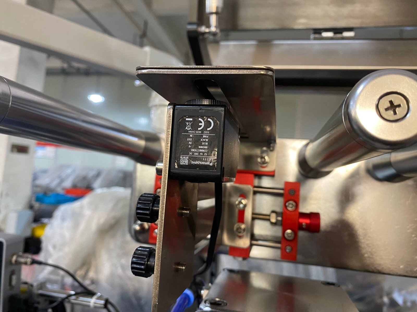
| Photoelectric Sensor | Imported 3-color mark sensor All colors detectable | Single-color sensor |
| Recipe Storage | 100+ recipes with one-touch recall | 10-20 recipes |
| Data Logging | 21 CFR Part 11 compliant (audit trail, user levels) | Basic logging |
| Failure Rate | <2% annual downtime 60% lower | 5-8% annual downtime |
Why Premium Control Systems Matter
Reliable automation = Consistent quality + Lower labor costs. Mitsubishi components aren't just a brand premium—they deliver real operational advantages:
- Precision: Servo-driven filling achieves ±0.1ml vs. ±0.5ml with stepper motors (5x more accurate)
- Uptime: Japanese PLCs have 10+ year lifespan vs. 3-5 years for generic brands (lower replacement costs)
- Compliance: FDA 21 CFR Part 11 data logging is mandatory for pharmaceutical export to US/EU markets
- Training: Intuitive HMI reduces operator training from 2 weeks to 3 days
Power Requirements & Installation
| Parameter | HIJ Specification | Notes |
|---|---|---|
| Power Supply | 380V 50Hz 3-Phase (customizable to 220V/60Hz) | Adapts to global standards |
| Total Power | 3.8kW | Energy-efficient design |
| Main Motor Power | 1.5kW | Premium efficiency motor |
| Compressed Air | 0.4-0.6 MPa at ≥0.3m³/min capacity | Standard workshop air |
| Cooling Water | Tap water or recycling system | For mold cooling |
| Machine Dimensions | 2,315×635×1,405mm (L×W×H) | Compact footprint |
| Net Weight | 820kg | Stable operation |
| Shipping Dimensions | 2,500×800×1,780mm (wooden crate) | Sea freight compatible |
| Noise Level | <75dB Quiet operation | OSHA compliant |
Why Installation Specs Matter
Right-sized infrastructure = Smooth installation + Lower operational costs. Key planning considerations:
- Space efficiency: 2.3m × 0.64m footprint fits standard cleanroom layouts (no facility redesign needed)
- Power consumption: 3.8kW total = ~$0.40/hour operating cost (vs. $0.70 for 6kW machines)
- Global compatibility: Voltage customization included = no need for expensive transformers
- Quick setup: Compact design allows installation in 1-2 days (vs. 5-7 days for large systems)
HIJ vs. Industry Average: Side-by-Side Performance
CE
Marking
Marking
GMP
Compliant
Compliant
FDA
Materials
Materials
RoHS
Compliant
Compliant
Need Detailed Technical Documentation?
Download our complete technical manual, IQ/OQ protocols, and material compliance certificates.
Regulatory Compliance
Industry Standards for Liquid Blister Packaging
Liquid blister packaging equipment must meet specific regulatory standards depending on the product type. HIJ machines are engineered to comply with all major international standards.
Pharmaceutical
FDA / EMA Standards
- 21 CFR Part 211Current Good Manufacturing Practice
- 21 CFR Part 11Electronic Records & Signatures
- USP <1207>Container Closure Integrity Testing
- EU GMP Annex 1Sterile Product Manufacturing
- WHO TRS 961Pharmaceutical packaging guidelines
Food & Beverage
FDA / EU Food Standards
- 21 CFR Part 110Food Manufacturing Practice
- EU Reg. 1935/2004Food Contact Materials
- HACCPHazard Analysis & Critical Control Points
- FDA 21 CFR 177Indirect Food Additives
- ISO 22000Food Safety Management
Industrial
Quality & Safety Standards
- ISO 9001:2015Quality Management Systems
- CE MarkingMachinery Directive 2006/42/EC
- REACHChemical Safety Regulations (EU)
- ATEXExplosive Atmospheres (where required)
- UL CertificationNorth American electrical safety
Complete Validation Package Included
HIJ liquid blister packaging machines are engineered to comply with all applicable standards for your industry. Every machine ships with full DQ/IQ/OQ/PQ validation documentation, material certifications (316L stainless steel), and FAT/SAT support.
Request Compliance Documentation →
Competitive Advantages
Key Features That Set HIJ Liquid Blister Machines Apart
Built on 20 years of industry expertise, every feature addresses a real customer pain point. Here's why leading manufacturers trust HIJ.
Precision Liquid Feeding System (316 Stainless Steel)
Pharmaceutical GradeThe heart of any liquid blister machine is its feeding system. HIJ's patented 316SS piston pump delivers ±0.1ml accuracy while handling products from water-thin serums to honey-thick pastes. Unlike generic systems that struggle with viscosity variations, our design ensures consistent dosing across your entire product range.
Interlayer Heating
Electric heating jacket maintains 30-80°C for viscous liquids (honey, chocolate sauce). Prevents clogging and ensures smooth flow without product degradation.
Removable Piston
Tool-free disassembly in under 3 minutes for CIP cleaning. No hidden corners where bacteria can hide—critical for GMP compliance and flavor-sensitive products.
GMP-Compliant Design
316SS material resists acidic/alkaline products. FDA/EU10/2011 certified. Electropolished to Ra≤0.4μm finish (no product adhesion, easy validation).
Why This Matters to You
- Cost savings: ±0.1ml accuracy means 2-5% less product waste vs. ±0.5ml systems
- Compliance ready: Complete IQ/OQ documentation included—pass FDA audits first time
- Faster cleaning: 15-min teardown vs. 45-min for welded systems (3x productivity gain)
- Product versatility: Handle 5cP to 5,000cP viscosity without hardware changes
Advanced Temperature Control to Prevent Product Degradation
Heat-Sensitive ProductsMany liquid products—probiotics, enzymes, cosmetic actives—lose efficacy above 60°C. Standard blister machines apply 180°C+ sealing temperatures that destroy these sensitive ingredients. HIJ's dual-zone heating system protects your product value while achieving hermetic seals.
Internal Heating Technology
Heats forming zone to optimal temperature (130-160°C for PVC) while keeping product cavity at safe 40-50°C. Thermal isolation prevents heat transfer to filled liquid.
±1°C Precision Control
PID temperature controller with Japanese Omron sensors. Maintains ±1°C stability across 8-hour shifts—no temperature drift that causes seal failures or product burning.
Rapid Cooling System
Water-cooled forming plates drop blister temperature to 35°C within 2 seconds post-sealing. Prevents heat-induced discoloration in cosmetics and loss of potency in pharmaceuticals.
Why This Matters to You
- Preserve active ingredients: Maintain 95%+ potency for probiotics, vitamins, enzymes
- Extend shelf life: Controlled sealing reduces oxidation—increase stability from 12 to 24 months
- Prevent discoloration: No browning in honey, no darkening in serums (premium appearance)
- Energy efficiency: Zone heating uses 30% less power than full-machine heating
Japanese Mitsubishi Control System
Premium ComponentsThe difference between 98% uptime and 92% uptime? The control system. HIJ exclusively uses Mitsubishi PLCs and servo motors—the industry gold standard in pharmaceutical manufacturing. While competitors cut costs with generic Chinese components, we invest in reliability because your production can't afford downtime.
Mitsubishi PLC + 10" HMI
Intuitive touchscreen interface with recipe storage (100+ formulas), real-time monitoring, and alarm history. Multi-language support (English, Spanish, French, German, Arabic).
Servo Motor Precision
Closed-loop servo control for filling pump (±0.01ml repeatability) and film feed (±0.1mm accuracy). Eliminates cumulative error that causes product giveaway in stepper systems.
Low Failure Rate
Mitsubishi components have 10+ year MTBF (Mean Time Between Failures) vs. 3-5 years for generic PLCs. Result: 60% fewer unplanned shutdowns, lower maintenance costs.
Why This Matters to You
- Higher OEE: 98% uptime means 6% more production days per year (worth $50,000+ annually)
- Faster training: Intuitive HMI reduces operator training from 2 weeks to 3 days
- Compliance: 21 CFR Part 11 data logging built-in (audit trail, user access control)
- Remote support: VPN-ready for HIJ engineers to diagnose issues remotely (no site visit delays)
Photoelectric Tracking for Perfect Seal Alignment
Zero Waste TechnologyMisaligned seals = product leakage = batch rejection = lost money. HIJ's imported 3-color photoelectric sensor detects registration marks on any film color (including metallic and transparent), ensuring each blister seals exactly where it should—every single time.
3-Color Sensor Technology
Red, green, blue LED array reads marks on white, black, gold, silver, and transparent films. Generic sensors fail on dark/metallic films—ours never miss.
Color Film Compatibility
Works with pre-printed brand films (logos, dosage instructions) without custom calibration. Saves you film production costs—no need for separate "machine-readable" films.
Zero Waste Operation
Auto-correction within 0.5mm prevents seal misalignment. Result: <0.1% rejection rate vs. 2-3% for manual/basic tracking systems. Save 20-30kg film per 10,000-unit run.
Why This Matters to You
- Reduce film waste: Save $3,000-5,000 annually on rejected material
- Premium packaging: Use branded films with confidence—no misaligned logos
- Faster setup: Auto-detection of film type eliminates manual calibration (5 min vs. 30 min)
- Quality consistency: Every blister meets hermetic seal standards—pass FDA leak tests
Food-Grade 304/316 Stainless Steel Construction
FDA/EU CompliantWhen your product directly contacts machine surfaces, material quality isn't negotiable. HIJ uses medical-grade 316SS for all liquid-contact parts and 304SS for structural components—ensuring zero contamination risk and meeting the strictest international food safety standards.
FDA/EU Compliance
Materials certified to FDA CFR 21, EU Regulation 1935/2004, and EU 10/2011. Complete material traceability documentation (Mill Test Certificates) provided for every machine.
Easy to Clean
Electropolished surfaces (Ra≤0.4μm) prevent product buildup. CIP-compatible design with no crevices. Meets 3-A Sanitary Standards for food equipment—validated cleaning protocols included.
Corrosion Resistant
316SS withstands acidic (pH 2-4) and alkaline (pH 9-11) products without pitting or discoloration. 20+ year service life vs. 5-7 years for carbon steel or 304SS in harsh environments.
Why This Matters to You
- Pass audits: BRC, FSSC 22000, HACCP inspections approved without remediation
- Product safety: No metal migration into products (ICP-MS tested—undetectable levels)
- Lower maintenance: Stainless steel = no painting, no rust, no part replacement from corrosion
- Higher resale: 304/316SS machines retain 60-70% value after 10 years (vs. 20% for painted steel)
Industry Solutions
Applications: Which Products Benefit from Liquid Blister Packaging?
From honey portions in 5-star hotels to pharmaceutical injectables in hospitals, HIJ liquid blister machines protect and portion products across industries. Discover how leading brands solve their packaging challenges.
Liquid Blister Packaging for Food Industry
Single-serve portions that extend shelf life, reduce waste, and elevate brand experience
Honey Portions for Hospitality
5-15ml per portion
24-month shelf life
Eco-friendly option
Customer Challenge:
Hotel chains need hygienic, single-serve honey for breakfast buffets. Glass jars are heavy, break easily, and have high theft rates. Plastic sachets leak and look cheap.
HIJ Solution:
Aluminum-plastic blister packaging provides tamper-evident seals, zero leakage, and premium appearance. Customizable shapes (hexagon = brand differentiation). Cost: $0.02-0.04/portion vs. $0.15 for glass mini-jars.
Salad Dressing & Ketchup Sachets
8-20ml per sachet
18-month stability
Recyclable aluminum
Customer Challenge:
QSR chains need sauce packets that don't burst in shipping, survive temperature fluctuations, and are easy for customers to open. Flexible pouches have 5-10% leakage rates in transport.
HIJ Solution:
Rigid blister structure survives 1.2m drop tests and -20°C to +50°C cycles. Peelable tab design requires no scissors. HIJ machines handle thick sauces (3,000cP+) without clogging—produce 4,000 sachets/hour.
Jam & Jelly Single-Serve Packs
10-25ml per pack
12-month shelf life
Heat-resistant
Customer Challenge:
Artisan jam producers want to enter airline/hotel markets but lack industrial filling capability. Manual filling into cups is too slow (50 units/hour) and inconsistent dosing leads to complaints.
HIJ Solution:
Automated blister filling reaches 1,200 units/hour with ±0.1ml consistency. Cold-form aluminum protects fruit color from UV light. Recipe storage allows switching between strawberry/blueberry in 15 minutes—perfect for small-batch producers.
Chocolate Sauce Portions
15-30ml per portion
9-month shelf life
Temperature stable
Customer Challenge:
Ice cream shops need chocolate sauce portions that don't crystallize in storage, flow smoothly at serving temperature, and have premium appearance. Pump dispensers cause cross-contamination and waste.
HIJ Solution:
Heated filling system (50°C) prevents crystallization during packaging. High-barrier PVDC film blocks oxygen—no fat bloom for 9+ months. Individual portions eliminate waste (exact 20ml serving vs. 25-30ml from pumps).
Packaging Food Products? Let's Design Your Custom Solution
HIJ food-grade machines meet FDA, EU, and HACCP standards. Free sample testing available.
Liquid Blister Packaging for Cosmetics & Personal Care
Sample-sized portions that drive trial, reduce returns, and protect active ingredients
Facial Serum & Essence Samples
1-3ml per sample
UV-protected
Active-preserving
Customer Challenge:
Premium skincare brands lose $50-100 in product returns for every $1,000 in sales due to customers buying wrong products. Pump-bottle samples oxidize within 24 hours of opening, giving false negative trial experience.
HIJ Solution:
Cold-form aluminum blisters block 100% light and oxygen—vitamin C serums remain stable for 18+ months. Single-dose packaging (2ml = 1 face application) eliminates contamination. Cost: $0.08-0.12/sample vs. $1.50 for pump vials.
Lotion & Cream Portions
2-5ml per portion
24-month stability
Hygienic
Customer Challenge:
Hotels want individual lotion bottles but bulk dispensers cause contamination concerns. Single-use plastic tubes are expensive ($0.30-0.50 each) and contribute to landfill waste.
HIJ Solution:
Blister portions cost $0.05-0.08 each—60% savings vs. tubes. Tamper-evident seal ensures hygiene. Aluminum-plastic construction is recyclable (vs. multi-layer tube material). HIJ machines handle thick creams (5,000cP+) without air bubbles.
Perfume Testers
0.5-1ml per tester
Alcohol-resistant
Tamper-proof
Customer Challenge:
Luxury fragrance brands lose 15-20% of tester product to evaporation/spillage in retail environments. Glass vials break during shipping. Magazine inserts (scent strips) provide weak fragrance impression.
HIJ Solution:
Hermetically sealed blisters prevent alcohol evaporation—100% strength preserved for 2+ years. Tear-open design releases full fragrance burst (better trial experience). Flat profile = magazine-insertable at $0.03/unit vs. $0.25 for vials.
Hair Care Treatments
5-15ml per sachet
18-month shelf life
Viscosity-adapted
Customer Challenge:
Salon professional hair masks in 200ml jars have 30% waste—clients use too much product per treatment. Once opened, active ingredients (keratin, collagen) oxidize within 3 months.
HIJ Solution:
Single-treatment portions (10ml = exact dose for shoulder-length hair) eliminate waste. Nitrogen-flushed blisters preserve protein actives—full efficacy for 18 months. Salons save $8-12 per treatment vs. jar usage.
Packaging Cosmetics? Protect Your Formulations with Precision
HIJ cosmetic-grade machines meet ISO 22716 (GMP for Cosmetics). Free stability testing available.
Liquid Blister Packaging for Pharmaceuticals
GMP-compliant solutions for oral liquids, topicals, and sterile products
Oral Liquid Medications
5-20ml per dose
GMP compliant
Child-resistant
Customer Challenge:
Pediatric syrups in glass bottles have dosing errors (caregivers miscalculate ml to teaspoon). Once opened, microbial contamination risk increases—especially in developing markets without refrigeration.
HIJ Solution:
Pre-measured single-dose blisters eliminate dosing errors—exact 5ml/10ml portions. Hermetic seal maintains sterility for 2+ years at 25°C/60% RH (WHO Zone IVb stable). Child-resistant peel tabs meet ISO 8317. Full IQ/OQ documentation for FDA approval.
Topical Ointments
1-5g per application
36-month stability
Tamper-evident
strong>Customer Challenge:
Antibiotic ointments in tubes have cross-contamination risk when tube tip touches infected skin. Patients overuse product (apply 2g instead of prescribed 0.5g)—leads to resistance development and increased healthcare costs.
HIJ Solution:
Single-use sterile blisters eliminate contamination—each application is fresh. Precise dosing (0.5g, 1g, 2g options) ensures correct treatment. Cost: $0.10-0.15/blister vs. $2-3 for 15g tubes (10-15 treatments)—similar per-dose cost with superior hygiene.
Gel Capsules (Semi-Solid)
0.5-2ml per capsule
Temperature-controlled
21 CFR Part 11
Customer Challenge:
Soft-gel manufacturers struggle with liquid-fill capsules that require specialized rotary die equipment ($500K+ investment). Manual filling into hard capsules has 5-10% leakage rate and lacks regulatory-compliant batch records.
HIJ Solution:
Blister packaging as alternative to soft-gels—fill liquid directly into thermoformed cavities. Temperature-controlled filling (30-40°C) handles oils, suspensions, and semi-solids. Electronic batch records with 21 CFR Part 11 compliance—audit-ready from day one.
Eye Drops & Nasal Sprays
0.3-1ml per dose
Sterile packaging
24-month sterility
Customer Challenge:
Multi-dose eye drop bottles require preservatives (cause irritation in 30% of users). Once opened, sterility cannot be guaranteed past 28 days—leads to wastage of 50-70% of product in each bottle.
HIJ Solution:
Preservative-free unit-dose blisters—gentler on eyes, suitable for post-surgical use. Blow-fill-seal alternative at 1/3 the equipment cost. Sterile filling in Class 100 environment with HIJ's optional isolator system. Zero waste—patients use 100% of purchased product.
Packaging Pharmaceuticals? Ensure Compliance & Patient Safety
HIJ pharma machines meet cGMP, WHO GMP, and EU GMP standards. Full validation support included.
Liquid Blister Packaging for Industrial Products
Precise portions for adhesives, lubricants, and specialty chemicals
Lubricants & Oils
5-30ml per pack
High viscosity
Leak-proof
Customer Challenge:
Bicycle shops need single-use chain lube portions but bulk bottles cause over-application (waste) and spills (contamination). Customers won't buy 100ml bottles for occasional maintenance—market penetration limited.
HIJ Solution:
10ml blister packs = perfect single-application dose for one chain. Retailers sell 5-packs for $3-5 (vs. $8-12 for bottle)—lower barrier to purchase. Blisters survive crushing in tool boxes—no leakage. Heated filling (60°C) handles thick oils smoothly.
Adhesives & Glues
1-10ml per pack
12-month shelf life
No curing risk
Customer Challenge:
Super glue in tubes cures after first use—70% of product wasted. Two-part epoxies require mixing (user error common). Industrial users need field-ready portions for on-site repairs without mixing equipment.
HIJ Solution:
Single-use blisters with pre-mixed adhesive—no curing in package due to hermetic seal (oxygen-free). Open, apply, done—zero waste. Two-part systems can use dual-cavity blisters with mixing applicator tip. Cost: $0.05-0.08/unit vs. $1-2 for tubes.
Sealants & Caulks
10-50ml per pack
Temperature-stable
Cartridge-free
Customer Challenge:
DIY consumers need sealant for small repair jobs but 300ml cartridges require caulking gun ($15-25). Once opened, cartridge tips clog—50% product waste is typical. Awkward to store partially used cartridges.
HIJ Solution:
Squeeze-tube style blisters with integral applicator tip—no gun needed. 30ml size = perfect for small bathroom/window repairs. Retailers sell multi-packs—capture DIY market at $2-3/blister vs. $8-12 for cartridges. HIJ machines handle paste viscosities (10,000cP+).
Diagnostic Reagents
0.5-5ml per test
Cold chain-free
Light-protected
Customer Challenge:
Clinical labs need single-use reagent portions but bulk bottles have contamination risk after first opening. Enzyme reagents degrade within 30 days of bottle opening—labs waste 30-40% of inventory. Cold chain storage adds $5-10K annual costs.
HIJ Solution:
Unit-dose blisters extend reagent stability to 18-24 months at room temperature—eliminate cold chain. Each test opens fresh reagent (no contamination). Nitrogen-flushed + UV-blocking aluminum = protect light/oxygen-sensitive enzymes. Labs reduce waste from 35% to <5%.
Packaging Industrial Liquids? Solve Dosing & Waste Challenges
HIJ industrial machines handle 5cP to 10,000cP+ viscosity range. Free feasibility testing available.
Ready to Transform Your Packaging?
Get Your Custom Liquid Blister Packaging Solution
Join 200+ manufacturers who trust HIJ for precision liquid packaging. Choose your next step below—whether you need detailed specs, want to see the machine in action, or are ready for a custom quote.
20+
Years Experience
ISO 9001
Quality Certified
CE & GMP
Compliance Ready
60+
Countries Served
Limited Availability: Only 3 expert consultations available this week for custom projects over $50K. Book yours now to secure priority engineering time.
Answering Your Questions
Frequently Asked Questions about Liquid Blister Packaging
Based on our 20+ years of experience, here are the most common questions our clients ask before investing in a liquid blister packaging solution.
How accurate is the liquid filling in blister packaging?
HIJ machines achieve exceptional accuracy of ±0.1ml per fill. This is 5x more precise than the industry standard (±0.5ml) achieved by machines using stepper motors. We accomplish this through:
- Japanese Mitsubishi Servo Motors: Provide closed-loop control for absolute precision and repeatability.
- High-Precision Piston Pumps: Machined from 316L stainless steel to pharmaceutical-grade tolerances.
What is the minimum and maximum fill volume?
Our standard machine configuration supports a wide fill volume range from 0.5ml to 50ml. We achieve this versatility through interchangeable piston pump heads and nozzles.
- Minimum Volume (0.5ml - 5ml): Ideal for cosmetic samples, perfume testers, and pharmaceutical unit-doses.
- Maximum Volume (up to 50ml): Perfect for food portions (dressings, sauces), industrial lubricants, or larger personal care products.
Can the machine handle different viscosities?
Absolutely. Our machines are engineered to handle a broad spectrum of viscosities, from water-thin liquids (1 cP) to thick pastes like honey or grease (up to 10,000 cP).
Key features that enable this include:
- Interlayer Heating Hopper: For viscous products like chocolate or wax, the hopper can be heated up to 80°C to reduce viscosity and ensure smooth flow.
- Powerful Servo Pumps: Provide enough torque to consistently pump thick materials without stalling.
- Anti-Drip Nozzles: Custom-designed nozzles prevent stringing and dripping for both thick and thin liquids.
How do you prevent leakage in liquid blister packs?
Leak prevention is paramount, and we guarantee a 99.9% seal integrity rate through a multi-layered approach:
- Optimized Sealing Parameters: Our Mitsubishi PLC precisely controls sealing temperature (±1°C), pressure, and dwell time for a perfect hermetic seal.
- High-Quality Molds: Molds are precision-milled to ensure even pressure distribution across the entire sealing surface.
- Advanced Sealing Options: We offer both heat sealing (for PVC/ALU) and optional ultrasonic sealing for temperature-sensitive films.
- In-line Leak Detection (Optional): We can integrate pressure decay or high-voltage leak detection systems for 100% quality control, essential for pharmaceutical applications.
What is the shelf life of liquid products in blister packs?
The shelf life is determined by the barrier properties of the packaging film, which our machine is designed to handle perfectly.
- PVC/ALU (6-12 months): Good for food products like jams and sauces, offering moisture protection.
- PVDC-coated PVC/ALU (18-24 months): Provides an excellent oxygen and moisture barrier, ideal for cosmetics and many oral pharmaceuticals.
- Cold-Form Aluminum (ALU/ALU) (36+ months): Offers a near-absolute barrier to light, moisture, and oxygen. This is the gold standard for highly sensitive pharmaceuticals and active ingredients, ensuring maximum shelf life.
How long does changeover take for different products?
We've designed our machines for rapid changeovers to maximize your uptime. A full changeover for a different product and blister size can be completed in just 15-20 minutes by a trained operator. This is 50-60% faster than older machine designs.
This is possible due to:
- Tool-free Mold Changes: Quick-release clamps and positioning guides.
- Recipe Recall System: The HMI stores all parameters (speed, temperature, fill volume) for 100+ products. Simply select the new product, and the machine adjusts automatically.
- Quick-Clean Pump System: The filling system can be disassembled for cleaning without tools in under 3 minutes.
Is the machine suitable for hot-fill applications?
Yes. The machine is perfectly suited for hot-fill applications up to 90°C (194°F). Our standard configuration includes a jacketed heating hopper with precise PID temperature control. This is ideal for products that need to be filled while hot to ensure sterility or maintain a liquid state, such as:
- Jams, jellies, and syrups
- Chocolate and caramel sauces
- Waxes and certain cosmetic balms
- Agar-based food products
What cleaning procedures are required?
Our machines are designed according to GMP (Good Manufacturing Practice) principles for easy and effective cleaning. The procedure is straightforward:
- Product Contact Parts: The entire 316L stainless steel filling system (hopper, pump, nozzle) is designed for CIP (Clean-In-Place) or can be quickly disassembled without tools for COP (Clean-Out-of-Place).
- Surface Cleaning: The machine's exterior is made of 304 stainless steel and anodized aluminum, allowing for easy wipe-down with standard cleaning agents like Isopropyl Alcohol (IPA).
Can I get a sample pack before purchasing?
Yes, absolutely! We believe you should be 100% confident in the final package. We offer a free sample testing service.
Here's how it works:
- You send us a small quantity of your liquid product and your desired packaging film.
- Our lab engineers run it on our demo machine, creating sample blister packs.
- We send the finished samples back to you for evaluation, along with a detailed report and video of the production run.
What is the lead time for delivery?
Our lead times are among the best in the industry, reflecting our efficient supply chain.
- Standard Machine: The lead time is typically 30-45 days from order confirmation and deposit.
- Customized Machine: For machines with significant customization (e.g., integrated cartoner, special robotics), the lead time is approximately 60-90 days.
Still Have Questions? We're Here to Help.
If your question wasn't answered above, or if you'd like to discuss the specific requirements of your product, our team of packaging experts is ready to assist. Let's build your perfect solution together.
Ask an Engineer