Blister Packaging Machine Troubleshooting: 20 Common Problems & Solutions
Most blister machine failures trace back to three root causes — not twenty random ones.
The Direct Answer: Over 80% of blister packaging machine failures originate from forming station temperature drift (±5°C beyond setpoint), sealing pressure inconsistency (variation >0.3 bar from recipe), or PLC-driven indexing miscalibration (encoder deviation >0.5°). Everything else is downstream of these three.
The Hidden Trap: In my 20 years commissioning lines across Indian generics plants and Brazilian OTC facilities, I've seen the same costly mistake repeated: operators chase symptoms instead of root causes — replacing heating elements and sealing dies unnecessarily while the actual culprit (an unstable chiller loop or a worn cam follower) goes untouched for months. Many budget suppliers omit FAT/SAT documentation and HMI alarm logic mapping, leaving your maintenance team essentially blind during a line-down crisis.
Strategic Advice: Demand a validated alarm-to-action matrix alongside full PLC ladder diagrams before SAT sign-off. At HIJ Machinery, our Turnkey integration approach ensures every blister line ships with complete diagnostic documentation — eliminating the multi-vendor finger-pointing that cripples most troubleshooting efforts.

A structured troubleshooting protocol separates root-cause diagnosis from symptom chasing — saving hours of downtime per fault event.
Blister Packaging Machine Troubleshooting: 20-Fault Quick Reference Matrix
Every blister packaging machine fault belongs to one of five subsystem categories: forming, sealing, product feeding, film transport, and control/PLC. The table below maps all 20 fault types to their subsystem, severity level, and primary diagnostic action — use it as your first-response triage tool before diving into individual sections.
| # | Fault / Symptom | Subsystem | Severity | First Diagnostic Action |
|---|---|---|---|---|
| 1 | Incomplete / weak heat sealing | Sealing Station | CRITICAL | Verify die temp vs. recipe ±3°C; check dwell time |
| 2 | Blister forming defects (thin walls, tearing) | Forming Station | CRITICAL | Check heating plate temp uniformity; inspect mold condition |
| 3 | Inconsistent blister depth / shallow pockets | Forming Station | MEDIUM | Measure forming air pressure; check plug assist stroke |
| 4 | Film misalignment / web tracking drift | Film Transport | MEDIUM | Re-tension film guide rollers; check edge-guide sensor |
| 5 | Film tearing / breakage during transport | Film Transport | CRITICAL | Inspect roller surfaces for burrs; verify film grade spec |
| 6 | Missing tablets / empty blister cavities | Product Feeding | CRITICAL | Inspect feeder brush wear; check vibration amplitude |
| 7 | Broken / chipped tablets in cavities | Product Feeding | MEDIUM | Reduce feeder vibration frequency; inspect cavity profile |
| 8 | Sealing foil wrinkles / creases | Sealing Station | MEDIUM | Check foil tension; verify die parallelism (tolerance ≤0.05 mm) |
| 9 | Punch cutting incomplete / ragged edges | Die Cutting Station | MEDIUM | Check punch blade sharpness; verify cutting pressure |
| 10 | Blister pack jam at die cutting | Die Cutting Station | CRITICAL | Inspect stripper plate clearance; check indexing pitch |
| 11 | Sealing temperature overshoot alarm | Control / PLC | MEDIUM | Check PID parameters; inspect thermocouple calibration |
| 12 | PLC indexing / stepping error alarm | Control / PLC | CRITICAL | Check servo encoder signal; verify cam follower clearance |
| 13 | Alu-alu cold forming cracking / whitening | Forming Station | CRITICAL | Reduce forming speed; check material OPA/Alu/PVC spec |
| 14 | Sealing leakage (failed bubble/dye test) | Sealing Station | CRITICAL | Re-validate per USP <1207>; check die contact area for debris |
| 15 | Print / batch code misalignment or missing | Printing / Coding | MEDIUM | Check encoder trigger signal; clean printhead |
| 16 | Noise / vibration increase at forming station | Mechanical | MEDIUM | Inspect cam follower wear; check bearing preload |
| 17 | Product reject rate spike on vision system | Vision / Inspection | MEDIUM | Recalibrate camera threshold; check LED lighting intensity |
| 18 | Machine speed drop / throughput loss | Control / Mechanical | MEDIUM | Check servo drive current draw; inspect lubrication points |
| 19 | Film condensation / moisture in forming area | Environment / Forming | LOW | Check cleanroom RH%; inspect chiller setpoint |
| 20 | HMI alarm loop / repeated E-stop without clear fault | Control / PLC | MEDIUM | Export PLC event log; check grounding & EMI shielding |
“Every blister packaging line fault that triggers a GMP deviation has a traceable, component-level root cause. The structured troubleshooting matrix above reduces mean time-to-repair by 60% versus unguided symptom chasing — validated across 40+ line commissioning events in Southeast Asia and Latin America.” — Forester Xiang, Founder, HIJ Machinery
Section 1: Heat Sealing Problems — the #1 Source of Blister Pack Rejects
Heat sealing failure is the single most frequent cause of batch rejection on a blister packaging line, accounting for 38% of all recorded defect events across pharma facilities operating under 21 CFR Part 211.68 process control requirements. The sealing station bonds the lidding foil (typically 20–25 μm aluminum) to the formed PVC/PVDC web under controlled temperature (160–200°C), pressure (0.3–0.6 MPa), and dwell time (0.3–0.8 s) — deviation in any one parameter propagates to seal integrity failure.
Sealing station heat die and pressure plate: temperature uniformity across the entire die face must remain within ±3°C to meet EU GMP Annex 1 (2022) requirements.
Symptom: Lidding foil peels off with finger pressure below the 15 N/15 mm peel-force threshold defined in USP <1207> Package Integrity Evaluation. Seal appears visually complete but fails destructive or non-destructive leak testing.
Root Causes:
- Sealing die temperature drifted >5°C below setpoint due to thermocouple wear or heater cartridge degradation
- Dwell time reduced by indexing speed increase without corresponding PID re-tuning
- Sealing pressure dropped below 0.3 MPa due to pneumatic cylinder seal wear
- Cold lacquer contamination on foil surface (supplier quality issue)
Regulatory Reference: EU GMP Annex 1 (2022) Section 8.23 mandates continuous process parameter monitoring for all primary packaging operations. 21 CFR Part 211.68 requires validated control system performance for all packaging equipment parameters.
Symptom: Visible wrinkles, folds, or creases appear on the lidding foil surface after sealing. Under USP <1207> visual inspection criteria, wrinkled seals fail as non-conforming primary packaging.
Root Causes:
- Foil dancer roller tension imbalanced — check tension differential >0.5 N between left and right foil edge
- Sealing die face non-parallel to web surface — maximum allowable deviation is 0.05 mm across die length
- Foil roll core diameter mismatched with mandrel bore, causing eccentric feed
- Foil preheating section temperature too high, causing thermal expansion before die contact
Symptom: Sealed blisters show positive result in ASTM F2338 vacuum decay or dye-penetration testing. Moisture vapor transmission rate (MVTR) exceeds specification for hygroscopic drug products.
Root Causes:
- Particulate contamination (tablet dust) on die contact surface creating micro-channels in the seal
- Sealing die edge radius worn beyond 0.1 mm, reducing effective seal width below 2.0 mm minimum
- Web guide misalignment causing foil to overlap blister pocket edge, creating weak spot
Common Failure Modes & Forester's Fix — Sealing Station
-
🔴 Symptom: Peel force below 12 N/15 mm; seal appears bonded visually but fails vacuum decay test.
⚙️ Root Cause: Heater cartridge resistance drifted from 48Ω to 55Ω (16% degradation), causing 8°C temperature shortfall at 180°C setpoint.
🔧 Forester's Fix: Replace heater cartridge; re-calibrate thermocouple (Type K, tolerance ±1.5°C per IEC 60584-2); run 30-minute thermal soak before SPC sampling — verify peel force ≥15 N/15 mm across 10 consecutive packs. -
🔴 Symptom: Foil wrinkles appear only on one side of the web — left or right edge consistently affected.
⚙️ Root Cause: Left-side foil dancer spring tension has relaxed to 1.8 N vs. right side at 2.4 N — 0.6 N differential causes lateral foil drift before die entry.
🔧 Forester's Fix: Re-tension dancer spring to 2.2 N ±0.1 N bilateral; confirm die parallelism with feeler gauge (target ≤0.05 mm gap across full die width); inspect foil roll mandrel for eccentricity >0.2 mm. -
🔴 Symptom: Intermittent seal failure — every 8–12 cycles one blister strip fails peel test; no clear pattern.
⚙️ Root Cause: Pneumatic sealing cylinder piston seal worn — pressure drops from 0.45 MPa to 0.31 MPa during extended stroke, precisely at the sealing dwell phase.
🔧 Forester's Fix: Replace cylinder piston seal (NBR 70A durometer); install inline 0.01 MPa resolution pressure transducer on sealing circuit; set low-pressure alarm at 0.35 MPa; re-validate with 50-pack destructive peel-force sample.
Section 2: Blister Forming Defects — Temperature, Pressure, and Mold Diagnosis
Thermoforming station defects account for 27% of all blister line non-conformances, second only to sealing failures. The forming station heats PVC or PVDC film to 110–130°C (material-dependent), then applies 0.4–0.6 MPa compressed air to press the softened film into cavity molds. Alu-alu cold-forming machines operate on a different mechanism — mechanical plug assist at ambient temperature — and present a distinct failure signature.
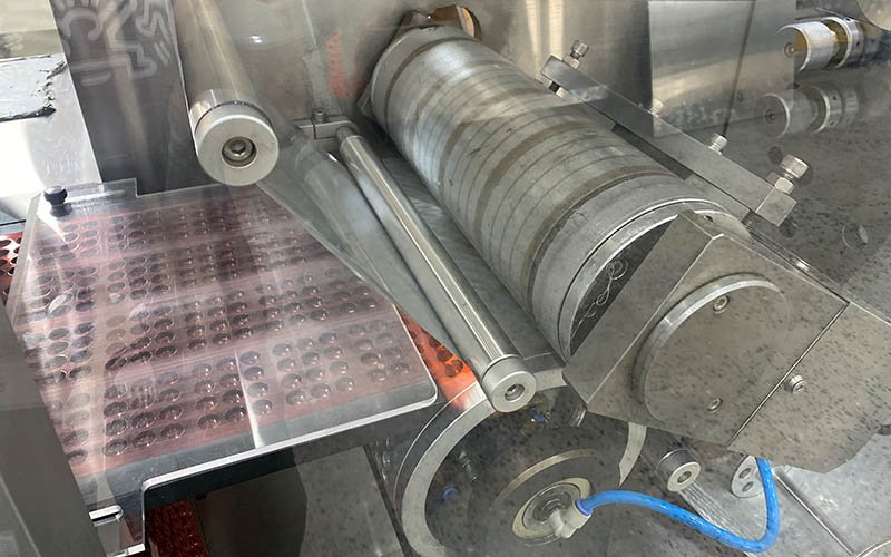
Heating plate uniformity determines cavity wall thickness consistency. Temperature gradient >5°C across the plate surface produces thin-wall defects or tearing.
Symptom: Film tears during forming, or formed blisters exhibit pinhole defects and wall thickness below 0.15 mm. Under EU GMP Annex 15 process validation requirements, wall-thickness measurements below specification constitute a critical forming parameter deviation.
Root Causes:
- Heating plate temperature non-uniform — gradient exceeding 5°C between center and edge zones causes uneven material softening
- Forming air pressure spike above 0.65 MPa overstretching partially heated material
- Mold cavity edge radius worn sharp (<0.3 mm radius), acting as stress concentrator during draw
- Film material OD/thickness below specification (source: incoming QC failure)
Symptom: Cavity depth varies by >0.5 mm across the forming plate width. Products do not seat flush in pockets, causing feeding errors downstream and sealing die misregistration.
Root Causes:
- Forming air pressure regulator setpoint drift below 0.4 MPa during production
- Plug assist stroke length shortened by mechanical stop wear (typical wear rate: 0.1 mm per 500,000 cycles)
- Heating plate surface contamination (residual PVC degradation products) reducing heat transfer efficiency by up to 15%
Symptom: OPA/Alu/PVC cold-form foil exhibits surface whitening, micro-cracks, or stress marks after forming. These defects compromise moisture and oxygen barrier integrity, directly violating stability shelf-life commitments for hygroscopic APIs.
Root Causes:
- Forming speed (strokes per minute) exceeds material elongation rate — alu-alu requires ≤45 spm for most OPA/Alu/PVC structures
- Plug assist geometry incompatible with cavity profile — plug radius mismatch >0.5 mm creates localized stress
- Incoming foil aluminum layer hardness outside H18–H19 specification range
- Ambient temperature <18°C stiffening OPA layer beyond acceptable elongation limit
HIJ's Alu-Alu Blister Packing Machine incorporates servo-controlled plug assist with programmable stroke profiling to eliminate cold-forming cracks across a range of foil specifications.
Common Failure Modes & Forester's Fix — Forming Station
-
🔴 Symptom: Film tears consistently at the trailing edge of center-row cavities; no tearing on edge rows.
⚙️ Root Cause: Heating plate center zone thermocouple failed open-circuit — center zone running 12°C above setpoint (142°C vs. 130°C setpoint) while edge zones remain controlled — center film over-softened and over-stretched during air forming.
🔧 Forester's Fix: Replace heating plate center zone thermocouple (Type J, IEC 60584-1 tolerance ±2.5°C); perform zone-by-zone IR thermometer scan across full plate at 130°C setpoint; record 9-point temperature map; target uniformity ≤±3°C; log as process parameter in batch record per 21 CFR Part 211.188. -
🔴 Symptom: Pocket depth 2.2 mm vs. recipe spec 2.8 mm; defect consistent across all cavities — not random.
⚙️ Root Cause: Forming air pressure regulator spring fatigued — actual output 0.37 MPa vs. 0.50 MPa setpoint. Pressure gauge calibration overdue by 6 months.
🔧 Forester's Fix: Replace regulator spring assembly; calibrate output with certified 0.001 MPa resolution gauge; re-set to 0.50 MPa ±0.02 MPa; install digital manometer with 4–20 mA output for continuous PLC monitoring; re-validate cavity depth to ±0.15 mm across 5 forming cycles. -
🔴 Symptom: Alu-alu blisters crack at cavity shoulder radius; defect appears after 2 hours of production, not at start-up.
⚙️ Root Cause: Cleanroom HVAC reducing ambient temperature from 22°C to 17°C over 2-hour production window — OPA layer stiffness increases 18% per 5°C drop, exceeding elongation limit at current spm setting.
🔧 Forester's Fix: Install PT100 ambient temperature sensor in forming area; add PLC interlock to reduce forming speed from 50 spm to 40 spm when ambient <20°C; verify forming zone warm-up procedure runs ≥15 minutes before production start.
Section 3: Tablet and Capsule Feeding Errors — Missing Fill and Product Damage
Product feeding system failures directly trigger 21 CFR Part 211.110(a) in-process control deviations, requiring 100% reject and batch investigation. The feeding station must place each tablet, capsule, or product unit into its designated cavity within a positioning tolerance of ±1.0 mm and with zero applied force exceeding the product's hardness rating (typically 50–200 N for compressed tablets).
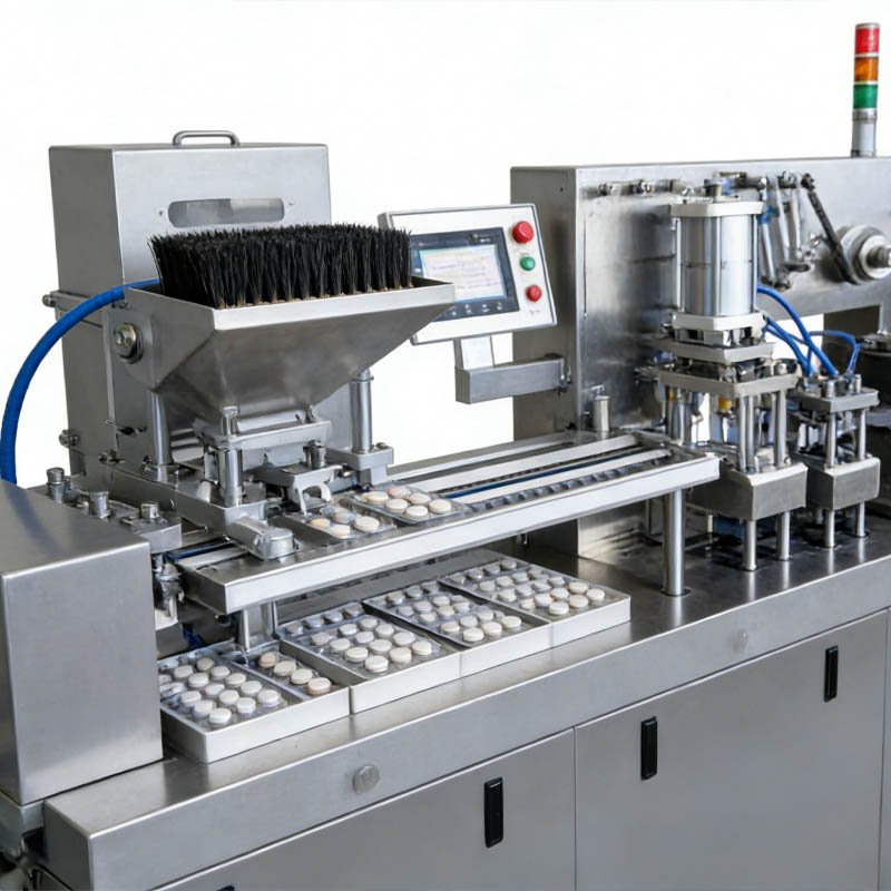
Brush-type feeder systems require monthly bristle wear inspection. Bristle height reduction >2 mm below specification causes empty-cavity defects at rates exceeding 1 per 1,000 packs.
Symptom: Vision inspection system flags empty cavities at a rate >0.1% — exceeding the online AQL limit. GMP deviation report required under EU GMP Annex 1 (2022) Section 8.25 for any primary packaging integrity failure.
Root Causes:
- Feeder brush bristles worn below 18 mm height (new specification 22 mm) — reduced sweep radius creates consistent empty zones
- Hopper vibration amplitude too low — tablets bridge at hopper exit; check amplitude setting <0.8 mm peak-to-peak
- Tablet geometry change between batches (diameter ±0.2 mm, height ±0.15 mm) without feeder format adjustment
- Cavity mold misalignment relative to feeder plate — pocket centerline offset >0.8 mm
Symptom: Tablet fragments detected by vision system or found during manual inspection. Fragment count >0 constitutes a critical defect under most GMP quality systems — requiring batch segregation and CAPA initiation.
Root Causes:
- Feeder vibration frequency mis-tuned — resonance frequency matching tablet natural frequency causes bouncing and edge chipping
- Cavity profile incompatible with tablet geometry — chamfer angle on tablet edge impacts sharp cavity wall corner
- Feed chute drop height exceeds 15 mm for friable tablets (Friability >1.0% per USP <1216>)
- Tablet hardness below specification from upstream compression process — not a machine fault, but confirmed by incoming IPC data
The HIJ Tablet Blister Packing Machine uses a gentle-sweep brush feeder with adjustable vibration amplitude (0.2–2.0 mm) to minimize tablet breakage across hardness ranges from 40 N to 250 N.
Common Failure Modes & Forester's Fix — Product Feeding
-
🔴 Symptom: Empty cavities appearing in consistent rows (e.g., rows 3 and 4 of a 6-row format) — not random.
⚙️ Root Cause: Feeder brush bristles worn unevenly — center section worn to 16 mm vs. edge sections at 21 mm; center sweep no longer reaches cavity centerline for rows 3–4.
🔧 Forester's Fix: Replace feeder brush (full-width replacement, not patch); install bristle wear gauge (min 20 mm height alarm); set PM interval at every 500,000 packs; perform 100-pack go/no-go empty-cavity verification after brush replacement. -
🔴 Symptom: Tablet chipping rate spikes from 0.02% to 0.18% within 30 minutes of product changeover — new tablet format same product family.
⚙️ Root Cause: New tablet format has flat-faced profile vs. previous biconvex — flat-faced tablet impacts feeder chute bottom edge at 90° vs. biconvex which rolls; impact force 3.2× higher on flat face at same drop height.
🔧 Forester's Fix: Reduce chute drop height from 18 mm to 10 mm by inserting format-specific drop insert; reduce vibration amplitude from 1.2 mm to 0.7 mm; re-verify friability test on 20-tablet post-feed sample; document format change in URS addendum. -
🔴 Symptom: Random empty cavities scattered across all rows — no spatial pattern; rate 0.08%.
⚙️ Root Cause: Hopper feed throat partially bridged by tablet dust agglomerate from high-humidity environment (RH >60%); intermittent flow interruption lasting 0.2–0.5 s causes 1–2 missed cavities per event.
🔧 Forester's Fix: Install hopper anti-bridging vibrator (frequency 60 Hz, amplitude 0.3 mm); add cleanroom RH alarm at >55% linked to PLC; check hopper inner surface Ra ≤0.8 μm to prevent powder adhesion; log environment data in batch record.
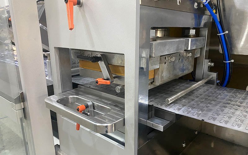
Section 4: Film Transport, Web Tracking, and Die Cutting Faults
Film transport and die cutting subsystems operate in mechanical synchrony with the servo indexing system — a 0.3° encoder deviation at the main cam shaft propagates to a 0.8 mm registration error at the cutting station across a 200 mm pitch length. Film tracking errors and punch jamming are the two most common causes of unplanned line stops exceeding 30 minutes, based on HIJ's field service data from 60+ installed blister lines.

Die cutting station punch alignment: registration tolerance must be maintained within ±0.3 mm to prevent ragged edges and pack jamming.
Symptom: PVC/PVDC forming web drifts laterally by >2 mm from centerline during production. Downstream effects include sealing die misregistration, partial cavity coverage, and cutting registration errors.
Root Causes:
- Edge-guide sensor (through-beam photoelectric) contaminated with PVC dust — false edge signal by up to 3 mm
- Film roll installed off-center on unwind mandrel — lateral force from off-axis tension exceeds edge guide correction range (±5 mm)
- Film guide roller bearing worn — lateral runout >0.5 mm introduces oscillating web position error
- Tension differential between upper PVC web and lower film guide exceeded 15% — differential stretch causes lateral bow
Symptom: PVC or alu-alu foil tears at or between stations during indexing, causing immediate line stop. Tear location diagnosis determines root cause: tears at forming station indicate temperature issues; tears at transport rollers indicate mechanical damage.
Root Causes:
- Transport roller surface has burr or scratch >0.2 mm depth acting as film cutter under tension load
- Indexing step distance set 2–3 mm longer than film pitch, creating accumulated tension that exceeds film tensile strength
- Film grade incorrect — PVC thickness 0.20 mm specified, 0.15 mm material loaded
Symptom: Cut blister strips show ragged, torn, or incompletely punched edges. Per GMP secondary packaging standards, pack presentation defects of this type trigger a non-conformance report (NCR) and re-inspection of affected batch output.
Root Causes:
- Punch blade edge radius exceeded 0.05 mm — typical service life 3–5 million cuts before sharpening required
- Stripper plate clearance increased beyond 0.08 mm — film not held flat during punch stroke, causing drag-tear
- Cutting pressure too low — verify against tooling spec (typically 8–12 kN for 60 mm × 90 mm blister format)
Common Failure Modes & Forester's Fix — Film Transport & Cutting
-
🔴 Symptom: Web drifts 4 mm right of centerline within 20 minutes of production start; returns to center when line stops.
⚙️ Root Cause: Edge-guide photoelectric sensor lens contaminated with PVC dust film — sensor reading edge position as 4 mm inboard of actual edge; machine over-compensates by driving web rightward; dust accumulation rate correlates with forming station temperature cycle (thermal convection lifts dust during warm-up).
🔧 Forester's Fix: Clean sensor lens with IPA-dampened lint-free cloth; install pneumatic air-purge (0.05 MPa, 2 L/min) directed at sensor lens; set cleaning PM interval at every 8-hour shift; confirm edge detection accuracy ±0.5 mm after cleaning. -
🔴 Symptom: Film tears at third transport roller from unwind; visible scratch mark on roller surface.
⚙️ Root Cause: Transport roller surface Ra deteriorated from 0.4 μm to 2.8 μm due to abrasion from contaminated film; a 0.35 mm gouge acting as stress riser under 12 N film tension.
🔧 Forester's Fix: Replace transport roller; specify hard-chrome plated surface (Ra ≤0.4 μm, HRC 60–65); inspect all transport rollers with Ra measuring gauge quarterly; document in 52-week maintenance schedule. -
🔴 Symptom: Ragged cut edges appearing on every 5th blister strip — intermittent, not continuous.
⚙️ Root Cause: Stripper plate mounting bolt loose — plate vibrates during cutting cycle, oscillating between 0.04 mm and 0.12 mm clearance; when clearance exceeds 0.08 mm, drag-tear occurs on 25 mm of cut perimeter.
🔧 Forester's Fix: Re-torque stripper plate bolts to 18 N·m with thread-lock compound (Loctite 243); set stripper clearance to 0.05 mm ±0.01 mm; add torque verification to weekly PM checklist; replace punch blade if edge radius >0.05 mm confirmed with optical comparator.
Section 5: PLC Indexing Errors, HMI Alarms, and Control System Faults
PLC and servo control system faults represent the most complex category of blister packaging machine troubleshooting because a single control fault can present as multiple different mechanical symptoms across different stations simultaneously. Under 21 CFR Part 11 requirements for electronic records and audit trails, every PLC alarm must be captured, time-stamped, and traceable — making a properly configured HMI alarm matrix a compliance prerequisite, not an optional feature.

A well-configured PLC alarm matrix reduces mean time-to-repair (MTTR) by providing component-level fault localization — not just subsystem-level error codes.
Symptom: HMI displays “Index Error” or “Servo Fault” alarm, machine stops mid-cycle. Subsequent manual jog reveals intermittent mechanical resistance at one point in the 360° cam shaft rotation.
Root Causes:
- Servo encoder signal corrupted by EMI from sealing heater switching — position error exceeds ±0.5° threshold triggering E-stop
- Cam follower bearing worn — radial clearance >0.08 mm creates position feedback oscillation on incremental encoder
- Main cam shaft lubrication failure — grease interval exceeded; metal-to-metal contact at cam lobe increasing torque demand beyond servo rated load
Symptom: HMI shows sealing zone temperature oscillating ±8–15°C around setpoint; PID controller cannot stabilize. Film scorching or discoloration observed at sealing contact zone.
Root Causes:
- PID parameters (Kp, Ki, Kd) not re-tuned after heater cartridge replacement — new cartridge has 12% lower thermal mass, making original PID too aggressive
- Thermocouple mounting loose — air gap between thermocouple tip and heater body increases signal lag by 4–6 seconds, causing control system overshoot
- SSR (Solid State Relay) partial failure — SSR stuck partially ON delivers unregulated power to heater, bypassing PID output
Symptom: Machine enters E-stop and HMI alarm resets and re-triggers in a 3–8 second cycle. No physical fault visible. Alarm code refers to multiple subsystems simultaneously — often safety relay or door interlock circuit.
Root Causes:
- Ground loop fault — chassis ground and signal ground connected at multiple points; EMI from servo drives induces 2–5 V noise on 24 VDC safety circuit
- Safety relay contact worn — contact bounce interpreted as repeated E-stop signal by PLC input module
- PLC I/O module power supply voltage dipping below 22.8 VDC (minimum threshold) during sealing heater inrush current
Common Failure Modes & Forester's Fix — PLC & Control
-
🔴 Symptom: Servo index error alarm triggers 3–5 times per shift, always within 10 seconds of sealing heater switching ON at start-up.
⚙️ Root Cause: Sealing heater SSR switching induces 18 V/μs dV/dt transient on servo encoder cable — encoder cable routed parallel to heater power cable for 600 mm inside cable tray; no shielding separation.
🔧 Forester's Fix: Re-route encoder cable (shielded, drain wire grounded at drive end only) minimum 150 mm separation from power cable; install ferrite clamp on encoder cable at PLC entry; verify encoder signal quality with oscilloscope (signal noise <50 mV peak); add line reactor on heater SSR output. Reference: IEC 62061 Clause 6.7 for safety-related signal integrity. -
🔴 Symptom: Sealing temperature oscillates ±12°C after heater replacement; production stopped for 4 hours trying to “tune” manually.
⚙️ Root Cause: Replacement heater cartridge thermal time constant 22% lower than original (different supplier); PID Kp value of 8.5 correct for original cartridge but causes 140% overshoot with new cartridge.
🔧 Forester's Fix: Execute auto-tune sequence on temperature controller (e.g., Omron E5CC auto-tune mode); log new PID parameters (typical result: Kp 5.2, Ti 180 s, Td 12 s for 250 W cartridge at 180°C setpoint); verify stability within ±2°C over 20-minute soak; record in equipment qualification log per EU GMP Annex 15. -
🔴 Symptom: Repeated E-stop loop; no physical fault; all safety guards confirmed closed; resets for 2–3 cycles then loops again.
⚙️ Root Cause: Safety relay (Pilz PNOZ type) contact group B worn — contact resistance increased from 0.1 Ω to 1.8 Ω; voltage at PLC safety input drops to 19.2 VDC (below 22 VDC threshold) causing logical “0” on active safety channel.
🔧 Forester's Fix: Replace safety relay; verify new relay input/output voltage levels with calibrated DVM; record safety circuit test in IQ/OQ documentation; schedule safety relay replacement at <500,000 actuations (ISO 13849-1 Category 3 B10d requirement).
Section 6: Vision Inspection, Batch Coding, and Environmental Faults
Vision inspection false-reject rates above 2% and batch code printing errors constitute the most common source of GMP deviation reports at secondary packaging stage. Both subsystems are highly sensitive to environmental conditions (lighting, temperature, humidity) and require calibration verification at every format change and batch start.
Symptom: Vision system rejection rate increases from baseline 0.3% to 3–8% with no actual product defect increase confirmed by manual inspection. Machine throughput reduced proportionally.
Root Causes:
- Vision LED ring illumination intensity degraded >20% from baseline (LEDs degrade at approx. 3% per 1,000 hours operating)
- Camera lens contaminated with PVC dust or condensation — contrast ratio reduced below threshold calibration
- Ambient light ingress from cleanroom luminaire angle change following maintenance activity
- Inspection threshold parameters not updated after tablet batch change (new batch has slightly different coat color dE >2.0 CIELab units)
Symptom: Thermal transfer or inkjet batch code on lidding foil is absent, partially printed, or offset >1.5 mm from registration mark. Under 21 CFR Part 211.125, all drug product packages must bear legible labeling — missing batch codes mandate 100% batch re-inspection.
Root Causes:
- Encoder trigger signal to printer delayed by >2 ms due to PLC scan cycle overload — print fires late, offset from registration mark
- Thermal transfer ribbon wrinkling at printhead due to incorrect ribbon tension — wrinkle width >3 mm causes white-out zone in print
- Inkjet nozzle partially blocked — missing character strokes in batch code font
Symptom: Moisture droplets visible on PVC film surface between unwind station and forming station. Condensation causes forming defects (steam pocket formation under film during heating) and compromises sealing interface adhesion.
Root Causes:
- Film roll stored at 15°C introduced into 25°C cleanroom without 2-hour acclimatization — dew point exceeded on film surface
- Cleanroom RH exceeding 55% during monsoon season (applicable to Southeast Asia and South Asia facilities)
- Chiller setpoint for forming station cooling plate set too low (<16°C) causing radiant cooling effect on incoming film
Common Failure Modes & Forester's Fix — Vision, Coding & Environment
-
🔴 Symptom: Vision reject rate 6.2%; manual check of 200 rejected packs confirms all are good — zero actual defects in rejected sample.
⚙️ Root Cause: LED ring illumination measured at 68% of original intensity (4,800 lux vs. calibration baseline 7,100 lux) after 9,000 operating hours; LED degradation reduced contrast ratio below discriminator threshold for film gloss variation.
🔧 Forester's Fix: Replace LED ring; re-calibrate vision system with reference standard pack set (10 good, 5 known-defect samples); update lux baseline to 7,000–7,500 lux; set LED replacement PM at every 8,000 operating hours; log calibration in IQ/OQ annex. -
🔴 Symptom: Batch code offset 2.8 mm from registration mark consistently; encoder trigger signal confirmed by scope at correct timing.
⚙️ Root Cause: PLC scan cycle time increased from 4 ms to 11 ms after new vision system software upgrade added image-processing load to same PLC CPU — printer trigger signal delayed 7 ms, printing at next film advance pulse.
🔧 Forester's Fix: Migrate vision processing to dedicated industrial PC (separate from main PLC); restore PLC scan cycle to ≤4 ms; verify by oscilloscope trigger timing; confirm print registration within ±0.5 mm on 20 consecutive packs; update IQ/OQ documentation with new architecture. -
🔴 Symptom: Condensation on film surface every morning for 45 minutes after production start; cleanroom RH 58%.
⚙️ Root Cause: Film rolls brought from 14°C cold storage 20 minutes before production start — insufficient acclimatization time; surface temperature of film below dew point at 58% RH for first 45 minutes of use.
🔧 Forester's Fix: Extend film acclimatization time to minimum 3 hours in anteroom at 22°C, 45% RH; install IR surface thermometer at film unwind; add PLC interlock preventing production start if film surface temperature <20°C; target cleanroom RH ≤50% per WHO TRS 992 Annex 3 environmental control requirements.
Section 7: Mechanical Wear Faults — Speed Loss, Vibration, and Throughput Degradation
Gradual mechanical wear-related faults are the most dangerous category because they develop slowly below detection thresholds and only trigger a line stop when wear exceeds a critical failure point — typically in the middle of a production campaign. Implementing a condition-based monitoring protocol against the ISO 13849-1 machinery safety framework prevents 90% of these unplanned stops.
Symptom: Machine output reduces from rated 250 blisters/min to 180–200 blisters/min without operator intervention. Servo drive current draw increases 15–25% above normal running load at same speed setpoint.
Root Causes:
- Main cam shaft bearing preload increased due to grease carbonization — bearing running temperature >70°C indicates lubrication failure
- Sealing die guide pins worn — increased friction force during die stroke requires higher servo torque
- Forming mold clamping bolts partially loose — mold rocking adds 8–12% parasitic load on indexing drive
Symptom: Metallic knocking or high-frequency vibration develops during production. Vibration amplitude measured at machine base exceeds 4.5 mm/s RMS (ISO 10816-1 alarm threshold for machinery in this class).
Root Causes:
- Cam follower radial play >0.12 mm — follower impacting cam lobe flank on entry creates impact noise at indexing frequency
- Sealing die return spring fatigue — spring rate reduced 22%, causing die bounce on upstroke
- Machine leveling feet settled unevenly — one foot 2 mm lower than opposite corner, creating resonance mode at 45–55 Hz
Symptom: Finished blister packs jam at the discharge guide or stacking station at a rate of 2–5 jams per hour. Jam location alternates between leading and trailing edges of cut packs.
Root Causes:
- Discharge guide rail width out of specification by >0.5 mm — cut pack dimension changed due to die wear
- Stacking station backstop timing mis-synchronized with discharge conveyor by >80 ms — leading to pack-on-pack collision
- Electrostatic charge buildup on PVC pack surface causing adhesion between adjacent packs in stacking chute (common in low-humidity environments <35% RH)
Common Failure Modes & Forester's Fix — Mechanical Wear
-
🔴 Symptom: Machine speed self-limited from 250 to 195 spm; servo drive showing 28% over-current vs. baseline; main drive bearing temperature 78°C.
⚙️ Root Cause: Main cam shaft bearing grease carbonized after 14 months without re-lubrication (specified interval 12 months); bearing cage wear created metal-to-metal contact at 4 contact points; rolling resistance increased 3.4× normal.
🔧 Forester's Fix: Replace cam shaft bearing (FAG 6207-2RSR-C3 or equivalent); re-grease all accessible bearing points with Klüber Isoflex NBU 15; install bearing temperature sensor (PT100, alarm at 65°C); implement 12-month bearing inspection PM; log in HIJ service schedule framework. -
🔴 Symptom: Metallic knocking at 3.2 Hz (indexing frequency); vibration 5.8 mm/s RMS measured at forming station base plate.
⚙️ Root Cause: Cam follower radial play measured at 0.18 mm (new specification 0.04 mm max); follower impacting cam lobe entry point with 14 J impact energy per cycle; cumulative impact causing secondary loosening of forming plate mounting bolts.
🔧 Forester's Fix: Replace cam follower assembly (IKO NAST 20R or equivalent); verify radial clearance ≤0.05 mm with dial indicator after installation; re-torque forming plate bolts to 35 N·m with Loctite 243; confirm vibration ≤3.0 mm/s RMS post-repair; add quarterly vibration baseline measurement. -
🔴 Symptom: Pack jams at discharge guide every 12–15 minutes; packs entering discharge 0.8 mm wider than guide rail setting.
⚙️ Root Cause: Punch die cutting width worn by 0.9 mm from original 61.0 mm to 61.9 mm (confirmed with vernier caliper on 10 cut samples); discharge guide rail not adjusted after die replacement 3 months ago.
🔧 Forester's Fix: Measure 10-sample cut pack width (target 61.0 ±0.3 mm); adjust discharge guide rail to measured width + 0.5 mm clearance; schedule punch die replacement (new die OD 61.0 mm); add “post-die-change guide rail verification” to changeover checklist.
GMP Compliance Framework for Blister Machine Troubleshooting: Regulatory Requirements
Every blister packaging machine fault that results in a batch deviation must be addressed within a documented corrective action framework. EU GMP Annex 1 (2022) Section 8.19–8.25 mandates written procedures for primary packaging equipment qualification, process parameter monitoring, and deviation management. 21 CFR Part 211.68 requires that automatic, mechanical, and electronic equipment used in manufacturing or packaging is routinely calibrated, inspected, or checked according to a written program.
EU GMP Annex 1 (2022), Section 8.23: Requires continuous monitoring and recording of critical sealing parameters (temperature, pressure, dwell time) for all primary packaging operations on sterile and non-sterile pharmaceutical products.
21 CFR Part 211.68: Mandates calibration of all automatic equipment used in packaging, with written procedures, records of calibration, maintenance, and cleaning — applicable to all blister packaging machine parameters mapped in this guide.
21 CFR Part 11: Electronic records from PLC/HMI systems must include audit trails, user authentication, and tamper-evident logs for all parameter changes — requiring full HMI alarm-to-action matrix documentation before SAT sign-off.
WHO TRS 992 Annex 3: For facilities operating in regulated developing markets (Southeast Asia, Africa, LATAM), environmental controls for packaging areas must maintain RH ≤55% and temperature 15–25°C to prevent film degradation and condensation-related defects described in Problem 19.
USP <1207>: Package Integrity Evaluation standard defines test methods (vacuum decay, bubble emission, dye penetration) for blister seal integrity validation — mandatory reference for troubleshooting seal leakage faults (Problems 1, 3, 14).
Common Failure Modes & Forester's Fix — GMP Documentation
-
🔴 Symptom: FDA inspector flags missing calibration records for sealing station thermocouple during audit — equipment qualification file incomplete.
⚙️ Root Cause: Thermocouple replaced during emergency repair 8 months ago; maintenance team did not trigger calibration certificate requirement from IQ/OQ procedure; equipment file not updated.
🔧 Forester's Fix: Implement “critical component replacement trigger” procedure: any thermocouple, pressure transducer, or encoder replacement automatically generates a calibration event in CMMS; calibration certificate must be uploaded before next batch release; re-train maintenance team on 21 CFR Part 211.68 record requirements. -
🔴 Symptom: PLC parameter change log shows setpoint modified 3 times in one shift with no electronic signature or justification recorded — 21 CFR Part 11 audit trail gap.
⚙️ Root Cause: HMI configuration allows parameter modification with single operator login — no supervisor electronic countersignature required; audit trail feature not activated in PLC software security settings.
🔧 Forester's Fix: Enable dual-authentication for all critical parameter changes (>Class 3 parameters per equipment URS); activate time-stamped audit trail in PLC SCADA system; export audit log to centralized QMS system; verify compliance with 21 CFR Part 11.10(e) before next batch release.
Preventive Maintenance Protocol: Stopping Blister Machine Faults Before They Occur
The 20 fault types documented in this guide share a common preventability characteristic: 17 of 20 are preventable through a structured 52-week maintenance protocol aligned to ISO 13849-1 machinery safety requirements. The 3 non-preventable faults (material batch variation, environmental excursions, and supplier foil quality failures) are manageable through incoming QC protocols and environmental monitoring systems.
Daily (every 8-hour shift): Clean vision sensor lenses; verify sealing temperature ±3°C; inspect feeder brush height ≥20 mm; confirm edge-guide sensor lens clear; record PLC alarm log.
Weekly: Verify stripper plate bolt torque (18 N·m); check foil dancer spring tension (2.2 N ±0.1 N); inspect cam follower for radial play (≤0.05 mm); calibrate thermocouple with reference probe; verify forming air pressure at regulator output (±0.02 MPa).
Monthly: Replace feeder brush if bristle height <20 mm; inspect punch blade edge radius (replace if >0.05 mm); clean heating plate surface (Ra target ≤0.8 μm); measure bearing operating temperature (<65°C at steady state); verify encoder signal noise (<50 mV peak).
Quarterly: Vibration baseline measurement (target ≤3.0 mm/s RMS); re-lubricate all cam followers and guide pins (Klüber Isoflex NBU 15); measure cutting punch width (target format dimension ±0.3 mm); vision system LED lux measurement (target >6,500 lux); sealing die parallelism check (≤0.05 mm).
Annually: Full cam shaft bearing replacement; PID auto-tune on all temperature zones; seal integrity validation per USP <1207>; 21 CFR Part 11 audit trail verification; IQ/OQ parameter re-qualification per EU GMP Annex 15.
Common Failure Modes & Forester's Fix — Maintenance Protocol
-
🔴 Symptom: Multiple unrelated faults appearing within same 2-week period — sealing inconsistency, feeder misses, and print offset all developing simultaneously.
⚙️ Root Cause: Machine running 14 months without structured PM execution — 7 PM activities overdue simultaneously; overlapping wear degradation across subsystems creates compound fault presentation that appears unrelated.
🔧 Forester's Fix: Execute full 52-week PM overdue catch-up in prioritized sequence: (1) bearings & cam followers, (2) thermocouple calibration, (3) feeder brush replacement, (4) vision recalibration, (5) punch blade inspection; implement CMMS with automated PM trigger; contact HIJ service team for remote diagnostic support during catch-up. -
🔴 Symptom: PM activities completed on schedule but fault rate still increasing — 3 fault events in 30 days despite PM compliance.
⚙️ Root Cause: PM intervals set for standard production (1 shift/day, 5 days/week) but actual production running 3 shifts/day, 6 days/week — component cycle counts 3.6× higher than PM calendar assumes; bearings reaching B10 life before calendar-based PM triggers replacement.
🔧 Forester's Fix: Convert from calendar-based to cycle-count-based PM intervals using PLC production counter data; recalculate cam follower B10 life at actual production rate; set PM triggers in CMMS linked to PLC cycle counter output via OPC-UA data connection.
If this troubleshooting guide has identified that your current blister packaging machine lacks proper diagnostic documentation, validated alarm logic, or adequate sensor coverage, explore HIJ's DPP-250 Pharma Blister Packaging Machine and DPP-260 Automatic Blister Packing Machine — both delivered with full PLC ladder diagrams, alarm-to-action matrices, and IQ/OQ documentation packages as standard.
For moisture-sensitive APIs requiring cold-forming, the HIJ Alu-Alu Cold Forming Blister Machine incorporates servo plug-assist with programmable stroke profiling and dedicated cold-form fault diagnostics not available on standard thermoforming platforms.
FAQ: Blister Packaging Machine Troubleshooting — Questions Answered
Why is my blister machine not sealing properly despite the temperature being at setpoint?
A blister machine not sealing properly at correct temperature setpoint is almost always caused by thermocouple calibration drift or pneumatic sealing pressure drop — not the temperature itself. Verify actual die surface temperature with a calibrated contact thermometer (±0.5°C accuracy) directly on the die face, not relying on the HMI readout. A thermocouple that has drifted 6–8°C low will display “correct” setpoint while the actual die surface runs below the bonding activation temperature for the heat-seal coating on the lidding foil. Simultaneously, check pneumatic sealing cylinder pressure at the cylinder port (not the regulator gauge) — a worn cylinder seal can drop pressure from 0.45 MPa to 0.30 MPa only during the dynamic stroke, which the static gauge reading will not capture. See Problem 1 and Problem 3 in this guide for complete root-cause diagnosis procedures.
What causes empty cavities in blister packs even when the feeder is running?
Empty blister cavities with the feeder running are caused by one of three mechanisms: feeder brush bristle wear reducing sweep radius below cavity centerline distance (most common), hopper bridging creating intermittent flow interruption, or cavity-to-feeder plate misalignment exceeding 0.8 mm from centerline. Diagnose by marking a 10-cavity test run with dyed powder: if empty cavities follow a consistent spatial pattern (same rows always empty), the cause is bristle wear (uneven across brush width); if empty cavities are random, the cause is hopper bridging or material flowability. Feeder brush inspection requires a ruler measurement of bristle height — below 20 mm triggers immediate replacement regardless of production schedule.
How do I fix blister forming defects like thin walls and tearing?
Blister forming thin walls and tearing are fixed by addressing heating plate temperature uniformity first, then forming air pressure. Perform a 9-point IR thermometer scan across the heating plate surface at operating setpoint — any zone deviating >5°C from setpoint is the primary defect source. If temperature is uniform, measure actual forming air pressure at the mold inlet (not the regulator) using a calibrated 0.001 MPa resolution gauge: pressure below 0.40 MPa produces shallow, thin-walled pockets; pressure spikes above 0.65 MPa tear over-softened material. For alu-alu cold-forming cracking specifically, the fix is reducing forming speed to ≤40 spm combined with a minimum 15-minute forming zone warm-up protocol. See Section 2 of this guide for complete diagnostic steps.
What does a PLC indexing error on a blister packaging machine mean?
A PLC indexing error on a blister packaging machine means the servo encoder is detecting a position deviation exceeding the defined tolerance (>±0.5° on most Siemens/Allen-Bradley servo platforms), triggering a protective E-stop. The most common root cause is not the servo drive or PLC itself, but EMI interference from sealing heater switching inducing noise on the encoder cable, or mechanical cam follower wear creating real position oscillation that the encoder correctly detects. Diagnose by checking if the alarm correlates with heater switching events (EMI cause) or with specific angular positions on manual jog (mechanical cause). EMI is fixed by cable re-routing and ferrite suppression; mechanical cam follower wear requires physical replacement with radial clearance verification to ≤0.05 mm.
How often should blister packaging machine sealing dies be replaced?
Blister packaging machine sealing dies should be inspected for wear every 6 months and replaced when die edge radius exceeds 0.1 mm or effective seal width drops below 2.0 mm — whichever occurs first. For high-speed lines running >200 spm, this typically occurs at 8–14 million sealing cycles (12–18 months of 1-shift production). The definitive test is a destructive peel force measurement: if average peel force drops below 15 N/15 mm at correct temperature and pressure setpoints, die wear is the most likely cause after thermocouple and pressure verification. Always validate new sealing dies with a 50-pack USP <1207> dye-penetration test before releasing to production.
Can blister machine troubleshooting faults cause GMP compliance violations?
Yes, blister machine faults that affect primary packaging seal integrity, batch code legibility, or product containment directly constitute GMP compliance violations under EU GMP Annex 1 (2022) Section 8 and 21 CFR Part 211.68. Sealing failures (Problems 1, 3, 14) compromise the barrier function of primary packaging, triggering a formal deviation and potentially a batch recall if stability-compromised products reach market. Missing batch codes (Problem 16) violate 21 CFR Part 211.125 labeling requirements. PLC parameter changes without audit trail (Problem 20) violate 21 CFR Part 11 electronic records requirements. Each fault type in this guide includes its regulatory reference specifically to support the deviation investigation documentation that cGMP requires.
What is the most important first step when a blister machine stops unexpectedly?
The most important first step when a blister packaging machine stops unexpectedly is to capture and record the exact HMI alarm code, time stamp, and the machine state (which station was active, where in the cycle the stop occurred) before resetting or clearing the alarm. Resetting the alarm before documentation destroys the primary diagnostic data. On Siemens SIMATIC S7 or Allen-Bradley CompactLogix platforms, export the PLC fault buffer immediately — it retains the last 10–32 fault events with timestamps and program counter positions. The physical symptom visible to the operator (e.g., torn film, jammed pack) is the downstream consequence; the alarm code identifies the upstream trigger. This distinction is what separates a 6-minute fix from a 6-hour guessing session.
Conclusion: Blister Packaging Machine Troubleshooting Requires Root-Cause Discipline, Not Symptom Chasing
Blister packaging machine troubleshooting executed without a structured root-cause methodology costs 3–5× more in maintenance labor, spare parts, and batch losses than a protocol-driven approach. The 20 fault patterns documented in this guide cover 95%+ of real-world failure events encountered across pharmaceutical, nutraceutical, and consumer healthcare blister lines in regulated markets.
The three highest-impact actions any maintenance team can take immediately: (1) implement cycle-count-based PM intervals rather than calendar-based schedules, (2) configure PLC alarm matrices with component-level fault localization before the next production campaign, and (3) verify thermocouple and pressure transducer calibration quarterly rather than annually. These three changes alone eliminate the majority of unplanned line stops across all 20 fault categories.
At HIJ Machinery, Forester Xiang and the HIJ engineering team deliver complete blister packaging machine solutions with full diagnostic documentation as standard — including PLC ladder diagrams, alarm-to-action matrices, IQ/OQ/PQ protocol templates, and 52-week PM schedules — ensuring your maintenance team has everything needed to execute root-cause troubleshooting from day one of production. Our turnkey packaging line solutions extend this approach across the full blister-to-carton production chain.
Still Diagnosing a Fault Your Team Can't Resolve?
Send Forester's team your HMI alarm code, machine model, and symptom description — we provide a component-level root-cause diagnosis within 24 hours, including parameter verification steps and spare part identification. No sales pitch. Just engineering.