
Feeding behavior
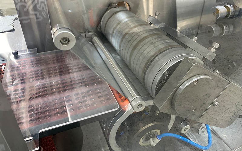
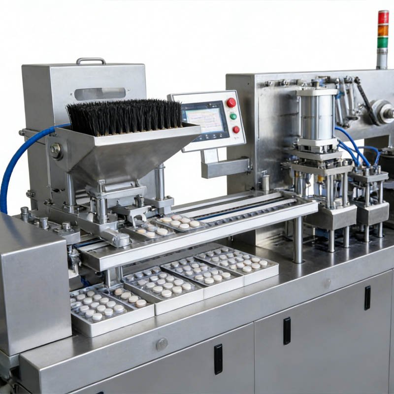
Dimensions, fragility, dust, orientation, static, bridging and representative challenge samples determine the feeder—not the model number.
Compare the two platforms by the approved product, blister drawing, materials, packs per stroke, accepted-output target, inspection boundary and FAT evidence—not by model number alone.
 DPP-260 platformMedium-speed flat-plate Alu-PVC / Alu-Alu reference
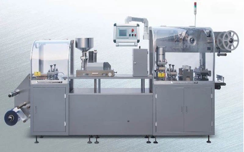 DPP-250 platformPublished DPP-250F Alu/Plastic / Alu/Alu reference
Reference images identify the machine families; the ordered station set, guards, controls and tooling are project-specific.
The DPP-260 reference has a 245 × 112 mm maximum forming area and 40–120 mm feed stroke. The published DPP-250F reference has a 250 × 112 mm maximum forming area and 30–120 mm stroke. The larger model number therefore does not prove a larger usable pack, a faster accepted output or a better project fit.
Choose only after both proposals use the same product, materials, blister drawing, feeder, inspection, reject logic, downstream interfaces and test conditions.
These are reference values from the available DPP-260/360K technical document and DPP-250F manual. They are not a promise for every configuration.
| Decision item | DPP-260 reference | DPP-250F reference | What the quotation must confirm |
|---|---|---|---|
| Process route | Flat-plate Alu-PVC / Alu blister packing platform | Published Alu/Plastic and Alu/Alu operating references | Exact forming route, station set and material construction |
| Maximum forming area | 245 × 112 mm | 250 × 112 mm | Approved blister drawing inside the usable tooling boundary |
| Feed stroke | 40–120 mm | 30–120 mm | Finished card length, index, print registration and perforation |
| Cycle-rate reference | 10–60 cycles/min depending on stroke and feeding difficulty | 20–50 cycles/min Alu/Plastic; 20–30 cycles/min Alu/Alu | Guaranteed test rate for the nominated product, feeder and material |
| Forming depth | 12 mm Alu-Alu; special-machine reference up to 25 mm | Confirm from the ordered format and approved drawing | Product clearance, draw ratio, wall thickness and seal land |
| Installed power reference | 11 kW | 7.5 kW | Destination voltage, frequency, options and utility schedule |
| Material reference | PVC/PVDC/PE forming web and PTP lidding references are documented | Alu/Plastic and Alu/Alu references are documented | Actual grades, thicknesses, roll drawings and sealing lacquer |
| Accepted output | Depends on packs per stroke, feeding and agreed operating factor | Depends on packs per stroke, feeding and agreed operating factor | Good packs during an agreed sustained run, with stops and rejects recorded |
Important: DPP naming is not a universal industry specification. The signed technical agreement, approved drawings and FAT protocol control the purchased machine.
Enter the cycle rate that each supplier will test, the finished packs produced per stroke, and a realistic operating factor. The worksheet makes the calculation visible; it does not replace a FAT guarantee.
Accepted packs/min = test cycles/min × packs/stroke × operating factor
A useful comparison separates verified fit from assumptions still requiring samples, drawings or trials.
Dimensions, fragility, dust, orientation, static, bridging and representative challenge samples determine the feeder—not the model number.
Cavity drawing, web width, stroke, forming depth, seal land, registration and cut position must fit the tooling envelope together.
Confirm printing, inspection, reject confirmation, card transfer, cartoning, utilities, guarding and data responsibilities.
Define run duration, materials, sampling, accepted packs, rejects, stops, deviations and retained records before the order.
These are screening conditions, not automatic recommendations. The final choice follows the approved pack and test plan.
Name each SKU, geometry, condition, batch and representative challenge sample.
Issue the cavity drawing, material grades, print controls and acceptance criteria.
State finished packs per stroke, sustained run, operating factor and reject accounting.
Compare feeder, tooling, inspection, coding, line interfaces, documents and services.
Sign the FAT method, sample plan, limits, retained data and deviation workflow.
A lower headline price can hide tooling, inspection, documents, test materials, line interfaces or site work. Put every cost driver in the same matrix.

| FAT decision | Method to approve | Evidence to retain | Question answered |
|---|---|---|---|
| Web handling | Approved material lot, reel setup, tension and splice method | Settings, tracking observations and deviations | Can the exact web feed consistently? |
| Forming repeatability | Approved samples, instruments, locations and limits | Cavity measurements, settings and defect log | Does the web form the approved geometry? |
| Seal process | Agreed appearance and integrity test method | Recorded settings, samples and results | Is there a usable window for the material pair? |
| Registration and cutting | Approved artwork, print mark, cut and perforation limits | Finished cards, measurements and observations | Does the pack match drawing and print controls? |
| Inspection and rejection | Defined challenge set and reject-confirmation method | Detection results, rejected packs and disposition | Are agreed defects detected and segregated? |
| Sustained run | Agreed duration, product, materials and operating condition | Total packs, accepted packs, rejects, waste, stops and interventions | Can the complete process meet the accepted-output target? |
A useful inquiry lets engineering compare the two platforms against one frozen boundary.
The published reference boundaries differ in forming area, stroke, cycle-rate ranges, utilities and platform configuration. DPP-260 lists a 245 × 112 mm maximum forming area and 40–120 mm stroke; the DPP-250F manual lists 250 × 112 mm and 30–120 mm. The purchase decision must use the approved pack, feeder, materials and FAT target.
No. Finished output depends on the tested cycles per minute, finished packs per stroke, feeding performance, material behavior, rejects, stops and the agreed operating factor. Compare accepted packs during the same sustained-run protocol.
In the available reference documents, DPP-260 lists 245 × 112 mm and DPP-250F lists 250 × 112 mm. This is why model numbers should not be treated as universal dimensions. The approved blister drawing must be checked against the specific quotation.
The available DPP-260 document describes an Alu-PVC / Alu platform and the DPP-250F manual includes Alu/Alu operating references. The exact forming route, depth, material construction, tooling and acceptance test must be confirmed for the ordered configuration.
A defensible comparison requires the same tooling sets, feeder, inspection, coding, line interfaces, documentation, FAT materials, shipping and site services. A base-machine price without those boundaries is not comparable, so current pricing should come from a configured quotation.
Do not assume that a model name establishes site compliance or that every document is included. State the applicable regulatory and quality requirements, then agree the document index, format, language, revision, approval responsibility and qualification support in the contract.
The FAT should use agreed product and material lots to test web handling, forming repeatability, feeding, sealing, registration, cutting, inspection, rejection and sustained accepted output. Retain settings, samples, measurements, rejects, stops and deviations.
Send product samples and dimensions, blister drawing, forming and lidding materials, card layout, target accepted output, batch structure, tooling list, inspection and coding scope, downstream interfaces, utilities, FAT criteria and required documents.
Send the product, pack, materials, accepted-output target and FAT boundary. HIJ can compare DPP-260 and DPP-250 against the same project definition.