Inspection engineering guide
A useful blister vision project starts with defined defects and ends with confirmed physical rejection. The camera is only one part of that evidence chain.
What is blister machine vision inspection?
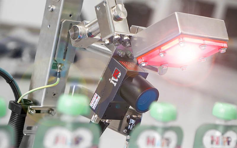
Blister machine vision inspection is a camera-based control function that acquires an image of a product, cavity, web or finished pack, evaluates defined visible characteristics and sends a decision to the machine control system. That decision may mark a pack for rejection, stop the machine, create an alarm or store a record, depending on the agreed control strategy.
This distinction matters during procurement. “Camera included” is not a usable requirement. A buyer needs to define the defect, where it becomes visible, the image quality needed to distinguish it, the action after detection and the evidence used to verify the complete response.
Start with the quality question, not the camera brand
A vision project should begin with a risk-based list of conditions that matter to product quality and pack acceptance. Each condition then needs a practical inspection method. Some are suitable for vision; others require leak testing, weight measurement, laboratory analysis, process monitoring or manual examination.
For every proposed vision check, write a plain-language question: “Is a tablet present in every required cavity?”, “Is the printed code readable and in the defined area?” or “Is visible product trapped in the seal land?” A specific question can become a test. “Inspect quality” cannot.
Where vision can sit in a blister line
The inspection location determines which defects are visible and whether there is enough time to act. Common positions include after feeding and before sealing, after sealing or printing, and near the finished-pack discharge. One line may use more than one inspection point because no single view exposes every relevant condition.
| Inspection point | Typical visible questions | Important limitation |
|---|---|---|
| After product feeding | Presence, count, position, gross shape, visible breakage, unexpected object or empty cavity | The pack is not yet sealed; later process defects are not visible. |
| Before or at sealing | Product in seal land, web alignment, gross contamination or cavity condition | Optical appearance does not establish final seal strength or leak performance. |
| After printing | Code presence, position, contrast, selected character or mark checks | Readability depends on print, web, glare, motion and the chosen verification method. |
| Finished pack | Pack presence, outline, registration, gross damage and selected printed features | Hidden product or seal defects may remain invisible from the available view. |
The complete inspection chain
A reliable result depends on more than an algorithm. The complete chain includes illumination, optics, sensor, trigger, image acquisition, image processing, classification, defect tracking, machine response, physical rejection and reject confirmation. Weakness anywhere in that chain can break the intended control.
- Present the target consistently. Product and web position must remain within the field of view and expected depth.
- Create a stable image. Lighting, exposure, focus and motion control must reveal the relevant feature with adequate contrast.
- Acquire at the correct instant. A trigger or encoder reference associates the image with the right machine index.
- Evaluate defined criteria. The recipe converts the image into measurements or classifications with controlled limits.
- Track the decision. The failed index remains associated with its physical pack through downstream motion.
- Execute and confirm the action. The machine rejects or stops as specified and records or reconciles the outcome.
Defects vision may be able to detect
Suitability depends on whether the defect produces a repeatable optical difference. Examples often considered during feasibility work include empty cavities, wrong counts, displaced products, visible chips or cracks, color differences, gross foreign material, product in a seal area, missing print, code position and pack registration.
The word may is deliberate. A small chip on a textured tablet, a transparent fragment over reflective foil or a subtle color change under variable ambient light can be difficult to separate from acceptable variation. Representative samples are needed before committing to a detection claim.
What a camera cannot prove on its own
Product attributes
- Chemical identity or potency
- Fill weight or dose
- Sterility or microbiological quality
- Internal cracks hidden from the view
Package attributes
- Seal strength or leak rate
- Barrier performance
- Material composition
- Defects obscured by product or opaque material
These attributes need their own controls and test methods. Vision may support the overall control strategy, but it should not be used as a substitute for a method that measures a different physical property.
Build a representative defect library
The defect library is the bridge between a quality requirement and a machine test. It should include known-good variation as well as representative examples of each defect class. Record the product, batch or source, format, defect creation method, severity, image, expected disposition and approval status.
A library made only from obvious defects produces an easy demonstration but a weak production challenge. Include boundary conditions: the smallest relevant chip, the least contrasting contaminant, the largest acceptable position shift and acceptable cosmetic variation that should not be rejected. Artificial defects should be justified because they may not reproduce real production appearance.
Define defect severity and acceptance before tuning
If operators tune thresholds while deciding what counts as a defect, the acceptance rule moves with the test. Quality, production and engineering should agree which conditions are critical, major, minor or acceptable before final recipe optimization. The categories do not have to use those exact labels, but each needs an expected machine action.
For example, an empty cavity may require rejection, while a harmless print-position variation within an approved window may remain acceptable. The system should not be tuned simply to maximize rejection or minimize rejection; it should separate the agreed populations with a documented margin.
Lighting is part of the measurement system
Lighting geometry, spectrum, intensity and stability often determine whether a defect is visible. Clear PVC, aluminum foil, glossy coatings and curved tablets can produce reflections that look like defects or hide them. Backlighting may emphasize shape and position, while diffuse or directional lighting may reveal surface features differently.
Record the selected light type, mounting, controller setting and shielding arrangement. If ambient light can reach the inspection area, challenge realistic changes. A recipe cannot reliably compensate for uncontrolled glare, dirt on a lens cover or a loose illumination mount.
Optics, field of view and resolution must match the task
Resolution should be derived from the smallest feature that must be distinguished across the required field of view, with allowance for focus, contrast, motion and processing. A camera’s megapixel number alone does not establish capability. Lens choice, working distance, perspective, depth of field and sensor sampling all affect the usable image.
A wide field may capture a full web but allocate fewer pixels to each tablet. Multiple cameras or a narrower field may improve feature visibility, but they add interfaces and test cases. Feasibility trials should use representative products and materials at the intended geometry.
Trigger timing and motion blur
The image must be acquired when the target is in a repeatable position. Intermittent-motion machines may trigger during a dwell; continuous-motion applications may need short exposure, synchronized illumination or encoder-based timing. Speed changes can affect image position and blur, so the operating range belongs in the test plan.
Trigger loss, duplicate triggers and timing outside the valid window require defined behavior. Depending on risk, the system may reject the affected index, stop the machine or alarm. “No image” must not silently become “good.”
Recipes and format changeover
A recipe normally ties inspection regions, thresholds, expected counts, timing and machine format to a defined product configuration. The project should specify who may create, approve, select and modify recipes; how the machine confirms the correct recipe; and what happens after a change.
Changeover checks can include camera position, focus, light setting, lens cleanliness, region alignment, reject timing and challenge samples. If mechanical adjustment is allowed, reference marks or controlled setup aids help operators reproduce the qualified condition.
Integrated system or retrofit?
Neither architecture is automatically superior. An integrated system may simplify timing and control interfaces because it is designed with the machine. A retrofit may be appropriate when the existing equipment, controls and mechanical space can support a well-defined inspection and rejection chain.
| Question | Integrated during machine build | Retrofit to an existing machine |
|---|---|---|
| Mechanical access | Camera, lighting and guards can be planned together. | Available space, vibration and safe access require a site assessment. |
| Timing and tracking | Can be designed into the original control sequence. | PLC signals, encoder references and downstream index mapping must be confirmed. |
| Responsibility | May have a clearer single-system boundary. | Machine OEM, vision supplier and site roles need explicit definition. |
| Validation impact | Can be planned with the new equipment qualification. | Change control and requalification scope depend on the modification and intended use. |
PLC and machine-control interfaces
The interface specification should identify every relevant signal: inspection ready, trigger, result valid, pass/fail, recipe identity, heartbeat, fault, bypass state, reject request, reject confirmation and reset. Signal timing, pulse duration and behavior on communication loss need values or testable logic in the project documentation.
Also define which controller owns the final disposition. If the vision processor reports a fail but the PLC owns index tracking, both systems must agree on the identity and timing of that pack. Diagnostic screens should make mismatches visible without allowing an operator to release an unconfirmed pack casually.
Track the defective pack through every downstream index
Detection and rejection may occur several machine cycles apart. The control system therefore needs a shift register, indexed queue or equivalent mechanism that associates each inspection result with the physical web or pack. Any operation that changes position—manual jog, restart, web splice, skipped index or jam recovery—can challenge that association.
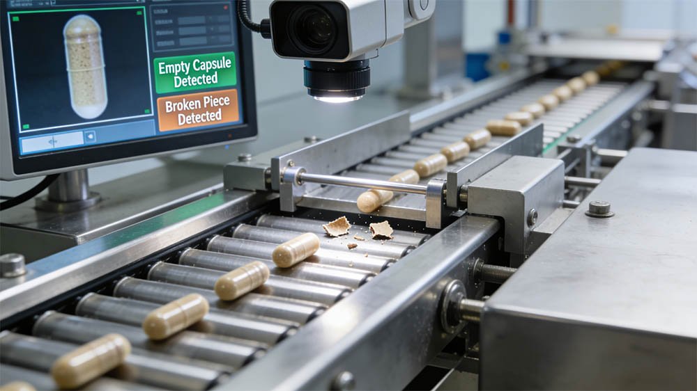
Validation should challenge the worst credible distance between detection and ejection, consecutive failures, failures at the first and last positions, controlled stops, power interruption where relevant and restart logic. The evidence should show that the intended defective pack—not its neighbor—was removed or otherwise controlled.
Physical rejection needs its own proof
A reject command is not proof that the pack left the accepted stream. The project should define the reject mechanism, timing window, confirmation sensor, fail-safe behavior, locked or controlled reject container and response to a full bin or blocked path.
Where individual reject confirmation is practical, the system can compare expected and confirmed rejects. Where it is not, an alternative reconciliation strategy must be justified. Rejected material should remain controlled until it is counted, investigated or destroyed according to the manufacturer’s procedure.
False accepts and false rejects
A false accept is a defective sample classified as acceptable. A false reject is an acceptable sample classified as defective. Tightening a threshold may reduce one while increasing the other, especially when good and defective image populations overlap.
Do not adopt a universal false-reject percentage or detection rate from a sales claim. Establish acceptance criteria from product risk, representative variation, challenge-set design and the intended use of the system. Report the test conditions and sample composition with the result so the number remains interpretable.
How to design a meaningful challenge set
A challenge set should represent the product and process window, not just ideal samples. Include approved good variation, each relevant defect class, boundary examples, different cavity positions and conditions that may alter image appearance. Randomize or blind the sequence when feasible so the operator cannot anticipate the result.
Keep a controlled master list that maps each sample to its expected result. After a test, reconcile presented samples, camera decisions, physical rejects and recovered samples. Investigate unexplained discrepancies rather than averaging them away.
Qualification follows intended use
The qualification strategy should be proportionate to how the system is used. A camera that provides operator information has a different role from a system that automatically determines pack disposition. The URS, risk assessment and validation plan should describe that role consistently.
| Stage | Vision-related focus | Example evidence |
|---|---|---|
| Design qualification | Requirements, defect visibility, architecture, interfaces, access and data needs | Approved URS, risk assessment, feasibility results and design review |
| Installation qualification | Installed components, software versions, drawings, connections and utilities | Component checks, calibration status, backups and controlled documents |
| Operational qualification | Functions, alarms, access, recipes, challenges, tracking and rejection across defined ranges | Approved protocols, raw results, deviations and traceable reports |
| Performance qualification | Routine product, trained operators and normal production conditions | Representative runs, reconciliations, trend review and approval |
| Continued verification | Drift, recurring defects, overrides, false rejects, maintenance and change | Periodic review, event records, trend data and requalification decisions |
For a broader qualification structure, see the tablet blister machine IQ/OQ/PQ guide.
Sample size is not a universal fixed number
The number of challenges should be justified by risk, the question being tested, expected defect frequency, confidence needs and the diversity of positions and conditions. Repeating one obvious defect many times is not equivalent to testing several relevant defect modes across the operating range.
Document how samples were selected and what conclusion the design supports. If a statistical claim is required, define the confidence method before testing. Otherwise, describe the exercise accurately as a functional or boundary challenge rather than implying more certainty than the design provides.
Electronic records and 21 CFR Part 11
The presence of a camera does not automatically make every screen or image a regulated electronic record. The assessment depends on the applicable predicate rules, intended use and whether electronic records are created, modified, maintained, archived, retrieved or transmitted in place of required paper records.
If the vision system creates regulated records, assess access control, authority checks, audit trails where applicable, record protection, accurate copies, retention, time synchronization, backup and system validation. Define whether data stays in the vision controller, moves to the machine HMI or is transferred to another system. The FDA’s Part 11 scope and application guidance explains the agency’s current enforcement approach; the manufacturer must determine how it applies to its records.
Alarms, bypass and failure modes
List credible failures and the required response: camera offline, no image, light failure, excessive rejects, processor fault, communication loss, reject not confirmed, bin full, wrong recipe and tracking mismatch. A fault should produce a state that operators can understand and resolve without weakening control.
If bypass is allowed, specify who can enable it, how it is indicated, whether production can continue, what alternate inspection applies and what record is created. Bypass should not be hidden behind a normal operator control or left active after the reason has ended.
Stops, jams and restart logic
Interruption handling is a frequent weak point because product can remain between the camera and reject station. The procedure and control logic should define what happens to inspected but not yet discharged indexes after an emergency stop, guard opening, jam, manual jog or power recovery.
A conservative strategy may clear or reject a defined zone after restart. Another design may preserve validated tracking state. Either approach needs documented boundaries and challenges; the correct answer depends on machine architecture and risk.
Cleaning, environment and maintenance
Dust, product fragments, condensation, vibration and cleaning residue can degrade images gradually. Inspection hardware should be accessible for controlled cleaning without making its position easy to disturb. The maintenance plan can include lens-cover inspection, illumination checks, mounting checks, focus verification and review of diagnostic trends.
After camera, lens, light, controller or software work, define what verification is needed before release. A component replacement that appears like-for-like may still alter image geometry or intensity.
Calibration and reference checks
Not every vision function uses a dimension traceable to a national standard, so “calibration” should not be used loosely. Identify which measurements require calibration, which settings require verification and which reference artifacts or challenge samples confirm continued suitability.
Reference samples can age, fade, deform or collect damage. Control their identity, storage, inspection and replacement. If digital reference images are used, protect versions and confirm that the displayed or processed image represents the current configuration.
Data review should support investigation
Useful data may include time, batch, recipe, cavity or lane, defect class, decision, alarm, user action and reject confirmation. Saving every full-resolution image indefinitely may be unnecessary or impractical; saving none may leave investigations without evidence. Define retention from regulatory, quality, storage and troubleshooting needs.
Trends can reveal feeder deterioration, recurring cavity positions, lighting drift or print instability, but only if categories and timestamps are reliable. A high reject count is a signal to investigate, not proof that the camera is performing correctly.
Responsibilities must cross the machine boundary
The machine supplier may provide hardware, software, interface documents and factory tests. The vision supplier may support optics and algorithms. The manufacturer remains responsible for product knowledge, intended use, approved defects, validation, operating procedures, data governance and batch disposition.
Put responsibilities in the quotation and contract. State who supplies defect samples, configures recipes, approves thresholds, writes protocols, executes site tests, resolves deviations, maintains backups and supports future formats. Undefined ownership often appears late as a validation delay.
What to include in a vision-system URS
The URS should describe required outcomes and boundaries without prescribing unnecessary implementation. The following list is a practical starting point:
- Products, blister formats and material families
- Required inspection locations
- Approved defect definitions and severity
- Smallest or boundary conditions to challenge
- Expected action for each result
- Operating speed and motion range to test
- Recipe and changeover controls
- User roles and access levels
- Trigger and PLC interface requirements
- Index tracking and reject confirmation
- Alarm, stop, restart and bypass behavior
- Data, image, audit and retention needs
- Cleaning and environmental conditions
- Documentation and training deliverables
- FAT, SAT and qualification responsibilities
- Backup, restore and change-control expectations
The companion blister packing machine URS guide can help place these controls in the wider equipment specification.
Turn the FAT into a traceable test matrix
A useful FAT matrix links each approved requirement to a test, sample, expected result and retained record. It should cover normal operation, boundary cases and relevant failures. Agree in advance which product and packaging materials will be available, who approves the challenge set and what happens if the test condition differs from the intended site condition.
| FAT area | Challenge | Evidence to retain |
|---|---|---|
| Detection | Approved good samples and each representative defect class | Sample identity, expected and actual decisions, images where agreed |
| Positions | Lanes, cavities, web edges and relevant orientations | Position map and reconciled results |
| Operating range | Defined speeds, stops, restarts and changeover conditions | Recorded settings, events and outcomes |
| Failure response | No trigger, camera fault, communication loss, bin full or reject failure | Alarm, machine response and recovery record |
| Tracking | Single, consecutive and separated defects across downstream indexes | Inspection-to-reject trace and recovered samples |
| Data | User access, record creation, retrieval, backup or audit functions in scope | Screen captures, exported records and protocol results |
How to assess a retrofit before quotation
A retrofit assessment should document the current machine model and serial number, drawings, PLC and HMI versions, available signals, encoder information, line speed, index distance, spare I/O, panel space, mechanical mounting space, guard impact, utilities, rejection method and downstream handling.
Representative product and material samples are also essential. A remote review can identify major constraints, but final feasibility may require measurements or a site visit. Do not promise a detection or tracking result from photographs alone.
Investigate recurring rejects systematically
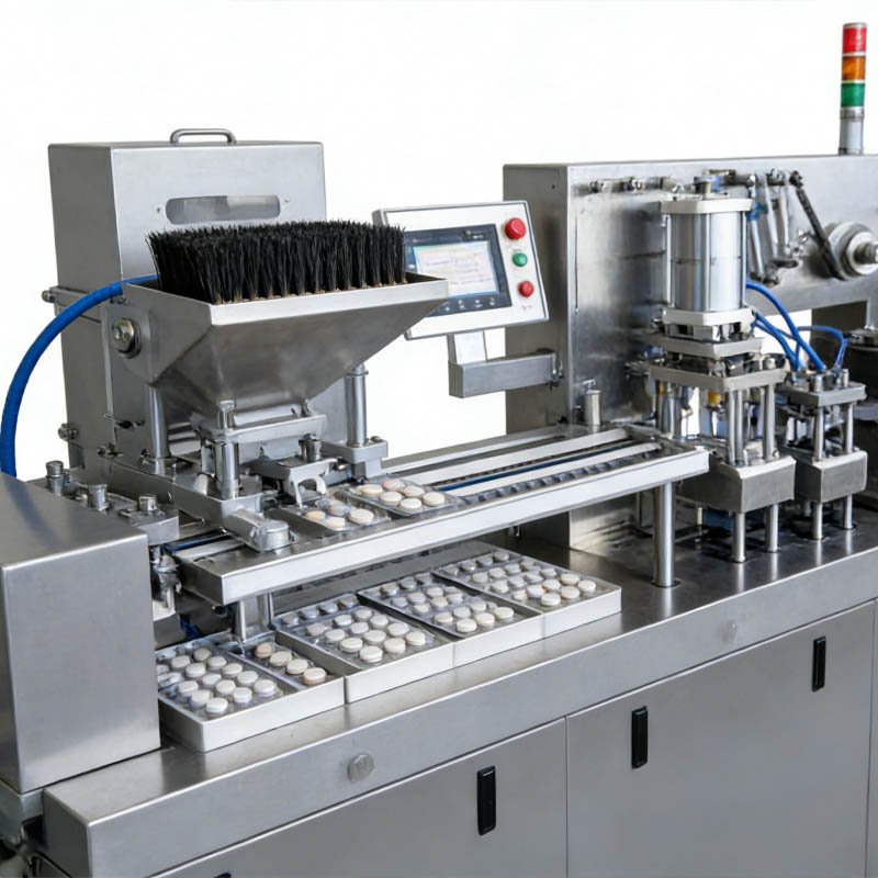
When rejects rise, first determine whether the product, presentation, image or decision has changed. Review examples from accepted and rejected populations; then check feeding, position, material reflection, lens cleanliness, lighting, trigger timing, recipe identity and recent changes. Avoid widening thresholds before the cause is understood.
A recurring cavity or lane pattern can indicate tooling, feeding or illumination geometry rather than a random product problem. Pair vision data with the tablet blister machine troubleshooting guide and the blister printing guide when the defect originates outside the camera system.
Questions to ask before selecting a supplier
- Which exact defect samples have been evaluated, and under what product and material conditions?
- Where will each camera and light be mounted, and how will they be protected and cleaned?
- How is each image associated with the correct machine index and final pack?
- How are reject commands confirmed and reconciled?
- What occurs after no image, lost communication, wrong recipe, stop, jog or restart?
- Which settings are product recipes, and who can modify or approve them?
- Which records are generated, where are they stored and how are they retrieved?
- What evidence, drawings, manuals, backups and test records are included?
- Who supports new products, software changes, troubleshooting and requalification?
Information needed for a useful technical proposal
Send product samples or clear dimensions and images, the blister drawing, forming and lidding materials, expected defect list, operating speed range, inspection location, reject concept, required records, regulatory context and intended FAT/SAT scope. For an existing machine, add the controller details, layout, videos of motion and the distance from inspection to rejection.
HIJ can then review whether the requirement is optically feasible, where the function should sit within the blister packing machine, and which risks need sample trials or further site information before commitment.
Frequently asked questions
Does a blister vision system guarantee 100% defect-free packs?
No. It can detect defined visible conditions within qualified limits, but it cannot eliminate every source of variation or prove non-visible attributes. Overall pack quality depends on the full process, controls, test methods and release system.
What defects can a blister vision system detect?
Depending on product, material and image conditions, it may detect missing or displaced products, visible chips or color differences, gross foreign material, product in the seal land, selected print defects and registration issues. Representative feasibility tests are needed for each required defect.
Can vision inspection verify blister seal integrity?
Not by appearance alone. Vision may detect selected visible seal-area conditions, but seal strength, channel leaks and barrier performance require suitable process controls and package integrity test methods.
Is an integrated vision system always better than a retrofit?
No. Integration can simplify interfaces, while a retrofit can be effective when the existing machine has suitable space, signals, tracking and rejection capability. The better option depends on the verified system boundary and responsibilities.
Does a blister camera automatically need 21 CFR Part 11?
No. Applicability depends on the predicate-rule records and how electronic records and signatures are used. If regulated electronic records are in scope, assess the relevant controls and validate the system for its intended use.
How should a vision system be challenged during FAT?
Use approved good variation and representative defects across relevant cavities, lanes, speeds and boundary conditions. Also challenge tracking, physical rejection, alarms, communication loss, stops, restarts, recipe control and any required data functions.
How do you validate reject tracking?
Introduce identified defects at known positions, follow their inspection decisions across the downstream index distance and reconcile the correct physical rejects. Include consecutive failures, stop and restart conditions, and relevant manual or fault recovery actions.
What should be included in a blister vision system URS?
Define products and formats, defect classes, inspection positions, acceptance and action rules, operating range, recipes, access, interfaces, tracking, rejection, alarms, restart behavior, data, cleaning, documents, training and qualification responsibilities.
Use the camera as one controlled link in the process
The strongest vision specification is not the one with the most features. It is the one that connects an approved quality question to a stable image, a controlled decision, the correct machine index, a confirmed physical action and reviewable evidence. That chain makes supplier discussions, FAT execution and later investigations far more productive.
Review your inspection and rejection chain
Share the product, blister drawing, materials, visible defect list, speed range and machine layout. We will identify the open feasibility, tracking and validation questions before a configuration is proposed.
Regulatory reading: EU GMP Annex 15, EudraLex Volume 4, FDA Process Validation guidance, 21 CFR 211.68 and 21 CFR 211.130. Regulatory applicability and validation strategy remain the manufacturer’s responsibility.