Blow-fill-seal technology guide
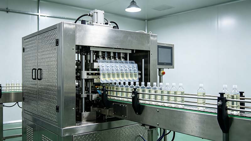
Blow-fill-seal, or BFS, is an integrated process in which a machine forms a container from thermoplastic material, fills it with product and seals it in one continuous automatic operation. For pharmaceutical use, that compact sequence can reduce separate container-handling steps, but it does not make a product or line automatically sterile.
A successful BFS project must define the product process, resin and container closure, exposure points, critical-zone protection, product-contact path, cleaning and sterilization strategy, inspection, integrity testing, qualification and accepted output. It must also distinguish true extrusion-based BFS from visually similar web-fed plastic-ampoule equipment.

Regulatory boundary: requirements differ for aseptically processed and terminally sterilized products, machine designs, container systems and markets. The product owner must establish the applicable contamination-control, validation and regulatory strategy with qualified specialists.
Definition
What blow-fill-seal means in pharmaceutical manufacturing
The definition matters because “form, fill and seal” describes a result, while BFS describes a particular forming route. A BFS machine normally melts polymer resin and extrudes it as a tubular parison. A mould closes around the parison, the container is formed, product is dosed and the container is sealed before the mould opens and the finished unit moves to later handling.
WHO identifies shuttle machines with a cut parison and rotary machines with a closed parison as common BFS types. Their exposure points, motion, output, tooling and control strategies differ. The buyer should name the intended machine type and product process rather than relying on the BFS abbreviation alone.
FDA’s aseptic-processing guidance notes that BFS can reduce human intervention and can bring economies in container-closure processing. The same guidance also identifies stages where the container or product may be exposed and requires those risks to be controlled. Integration reduces transfers; it does not eliminate the need for process understanding and validation.
Process sequence
How the BFS cycle forms, fills and seals a container
Machine designs vary, but the project can be reviewed as a sequence of connected control points. Every stage must protect the identity, quality and required state of the product and container system.
Do not turn this sequence into universal settings. Resin, product, container size, mould, extrusion head, machine architecture and required product state all affect the validated operating window.
Technology boundary
Separate true BFS from web-fed plastic-ampoule form-fill-seal
Plastic single-dose ampoules can be made by different equipment families. Their finished appearance does not identify the process. A true BFS line starts with thermoplastic granulate and extrusion of a parison. A web-fed ampoule line starts with rollstock film or sheet, forms cavities from the web, fills them and seals them with another web or formed layer.

| Question | Extrusion-based BFS | Web-fed ampoule form-fill-seal |
|---|---|---|
| Starting material | Approved thermoplastic granulate supplied to an extrusion system. | Approved rollstock film or sheet supplied to a forming web path. |
| Container formation | An extruded parison is enclosed and shaped in a mould. | Flat web is formed into cavities using the machine’s thermoforming process. |
| Closure creation | The container is closed as part of the moulding and sealing cycle. | A second web or opposing formed layer is sealed to the filled cavity. |
| Primary machine questions | Resin handling, extrusion, parison control, mould, filling assembly and seal formation. | Roll data, web heating and forming, registration, lidding or opposing web, sealing and cutting. |
| Qualification | Must address the actual BFS architecture, product process and intended control state. | Must address the actual web-fed process, materials, seal and intended control state. |
This distinction prevents an RFQ from comparing machines that cannot execute the same process. Begin every inquiry with the starting material—resin or rollstock—and a controlled drawing or sample of the intended container.
Sterile-product scope
BFS can support aseptic processing, but it is not automatically aseptic
BFS is used for products with different sterility and processing strategies. Some products are aseptically processed; others may be terminally sterilized if the product and container system support that route. Non-sterile applications have another risk and control profile. The machine label does not decide the product pathway.
For aseptically processed sterile products, the contamination-control strategy should connect facility, utilities, equipment, personnel, material transfer, sterilization, cleaning, environmental monitoring, interventions, aseptic process simulation and container-closure integrity. EU GMP Annex 1 and WHO sterile-product GMP contain BFS-specific considerations within that wider system.
Exposure and intervention questions
- Where can the forming container interior or sterile product contact the surrounding environment?
- Which air or gas supplies contact the product or critical surfaces, and how are they filtered and monitored?
- How are the product path, filling assembly and relevant product-contact surfaces cleaned and sterilized?
- Which routine and non-routine interventions can occur, who may perform them, and how are they qualified?
- How are start-up, stoppage, restart, alarm recovery, component replacement and maintenance represented in validation?
- How is the machine’s surrounding environment justified for the actual design and product process?
Do not copy a cleanroom class from a sales page. Current regulatory texts distinguish machine designs and processing strategies. The manufacturer must justify the environment and critical-zone protection through contamination-control and process evidence.
Container system
Qualify the resin, formed container and product together
The container is created inside the machine, so resin and process controls are directly connected to container dimensions, surface, strength, seal and product contact. The approved material specification should identify the resin grade, supplier, additives or colorants where applicable, handling, testing, release and change-control requirements.
Container design must support dose delivery, opening, administration, storage, transport, coding and secondary packaging. Wall-thickness distribution, neck or twist-off geometry, seal profile, residual flash, particulate risk and mechanical performance depend on the mould and operating window.
| Evidence area | What to define | Why it matters |
|---|---|---|
| Material identity | Exact resin grade, approved supplier, additives, incoming tests and change notification. | Material variation can affect processing and product-contact suitability. |
| Compatibility | Product interaction, sorption, permeation, extractables and leachables strategy as applicable. | The machine trial cannot establish long-term product compatibility. |
| Container drawing | Nominal geometry, tolerances, fill volume, opening features, markings and critical dimensions. | Controls tooling, dose presentation, user handling and inspection. |
| Closure and integrity | Seal geometry, relevant defects, test methods, sampling and acceptance criteria. | A visually closed container may still require defined integrity evidence. |
| Stability | Proposed container closure, storage, shelf life and approved study design. | Product quality over time is not proven by a short equipment run. |
| Distribution | Secondary pack, route, vibration, compression, temperature and handling profile. | Mechanical and environmental stresses can interact. |
FDA’s container-closure guidance describes information expected for packaging systems used with human drugs and biological products. Apply the current product- and market-specific requirements rather than treating one resin name as approval of the complete package.
Critical process controls
Control the connected process instead of one headline parameter
BFS integrates several unit operations, so a change in one stage can appear as a defect later. A dimensional problem may begin with resin or extrusion. An integrity defect may begin with mould alignment, product on the seal area or the timing of the filling assembly. A fill-volume trend may reflect the product supply system rather than the forming section.
Control limits and alarms must come from development, equipment capability and validation. A supplier’s general range is not a product recipe. Define who may change each parameter, how changes are recorded and how the process returns to an approved state.
Cleaning and sterilization
Design the product path and changeover before approving the layout
Where BFS is used for sterile products, WHO states that the full system is sterilized after connections are made. The project must define the product-contact boundary, connection method, cleaning and sterilization cycles, condensate and drain behaviour, filters, hold times, monitoring, acceptance and release.
Review the path from prepared bulk product to the filling point. Identify tanks, pumps, valves, hoses or fixed piping, filters, manifolds and filling assemblies. Each part needs a defined state before, during and after processing. Dead legs, difficult drains, trapped air or inaccessible surfaces should be addressed in design review rather than left to operating procedure.
Changeover questions
- Which components remain in place, which are removed and which are single use?
- How are parts identified, protected, transported, cleaned, sterilized and reassembled?
- How are previous product, resin, labels, containers and records cleared and reconciled?
- What verifies cleaning, sterilization and correct assembly before the next batch?
- How are filter integrity, cycle records, alarms and deviations reviewed?
- Which product and process hold times are established and monitored?
A fast mechanical format change is only one part of total changeover. Include product-path work, cleaning, sterilization, line clearance, environmental recovery where applicable, setup, verification and the first accepted output.
Inspection and integrity
Define how every finished container is accepted or rejected
The inspection plan should begin with the defect list and risk assessment. Possible attributes include container dimensions, visible polymer defects, flash, closure condition, fill quantity, particulate observations, code and artwork, opening feature, leak or integrity result and appearance after secondary packaging.

EU GMP Annex 1 connects form-fill-seal technologies with container-closure integrity expectations and requires a risk-based control strategy. Select test methods that detect the relevant failure mechanism at the needed sensitivity. Visual inspection can find some defects but does not replace a validated integrity method where one is required.
Automated checks need challenge samples or simulations that are controlled and reconciled. Demonstrate detection, decision, tracking, physical rejection, reject confirmation and secure collection. Include planned stops, restart, alarm recovery and transfer to downstream equipment, because tracking can fail even when the detector makes the correct decision.
Sampling plans should identify locations within the mould or container group, start-up, steady operation, restart and the end of the run. Record the relationship between samples, process data, resin lot, product batch, tool and time.
Qualification
Connect design review, FAT, SAT and process validation
Design qualification should show how the proposed machine and facility concept address the approved URS and risk assessment. Installation qualification verifies the installed system and documented components. Operational qualification challenges defined operating functions and ranges. Performance qualification demonstrates the process with the buyer’s approved products, people, procedures and site conditions.
For aseptic processing, aseptic process simulation belongs to the manufacturer’s validation program. It should represent the process, duration, interventions, shifts and challenging conditions defined by the applicable guidance and contamination-control strategy. A supplier FAT does not replace site aseptic process simulation or batch-release decisions.
| Stage | Useful BFS evidence | Does not prove alone |
|---|---|---|
| Design review / DQ | URS traceability, process boundary, material and personnel flow, critical-zone concept, utilities, controls and risk actions. | Installed condition or routine process performance. |
| FAT | Agreed machine functions, tooling, alarms, records, run states and selected container results at the supplier site. | Site environment, sterile-product validation or commercial shelf life. |
| SAT / IQ | Receipt, installation, utilities, components, calibration basis, documents and site interfaces. | Performance with every product and intervention. |
| OQ | Authorized operating ranges, controls, alarms, recipes, sequences, challenges and recovery states. | Commercial consistency with the final product and procedures. |
| PQ and aseptic validation | Approved product, resin, tooling, operators, procedures, environment, interventions, sampling and acceptance evidence. | Future uncontrolled changes or automatic continued compliance. |
Agree document ownership before purchase. Equipment drawings, manuals, certificates, software documents and supplier test records can support the buyer’s validation, but they do not make the equipment vendor the owner of the drug-product process.
URS and RFQ
Give suppliers the inputs that determine a BFS configuration
- product identity, dosage route, sterile or non-sterile strategy and terminal-sterilization status;
- product properties relevant to pumping, filling, temperature, foaming, particles, hold time and contact materials;
- target dose, fill range, accuracy definition and sampling method;
- container drawing, units per mould or group, opening system, markings and secondary package;
- approved or candidate resin grade, supplier data, handling and change-control requirements;
- product-contact path, filtration or other preparation, cleaning and sterilization strategy;
- facility concept, critical-zone protection, utilities, environmental monitoring and material flow;
- inspection, integrity, coding, rejection, reconciliation and data requirements;
- accepted containers per batch or hour, run duration, changeovers and downstream interfaces; and
- FAT, SAT, qualification, training, manuals and lifecycle-support scope.
If the intended starting material is rollstock rather than resin, state that clearly and request a web-fed form-fill-seal proposal. The plastic ampoule filling and sealing page represents that separate project family.
For a true extrusion-based request, the supplier must confirm its BFS machine architecture and scope in writing. Do not infer BFS capability from a page title, container photograph or the phrase “integrated filling and sealing.”
Capacity and cost
Measure accepted containers across the complete batch
Maximum cycles are not saleable output. Calculate the number of containers per mould or cycle, verified cycle rate, planned run time and operating factor, then subtract rejected units and losses. Include resin changes, product-path preparation, cleaning or sterilization, environmental release where applicable, start-up, sampling, stops and downstream constraints.
Cost comparison should use the same product and acceptance boundary. Include resin and product yield, utilities, moulds, format changes, inspection, integrity testing, labour, cleaning and sterilization, environmental controls, maintenance, waste, secondary packaging and validation work. Compare BFS with a conventional or web-fed route only when both can meet the product requirements.
Primary references
Use current regulatory sources within their stated scope
Questions from project teams
Blow-fill-seal technology FAQ
What is blow-fill-seal technology?
Blow-fill-seal is an integrated automatic process that forms a container from thermoplastic material, fills it with product and seals it in one continuous operation. Pharmaceutical BFS normally starts with thermoplastic granulate that is melted and extruded as a parison.
Is every plastic ampoule machine a BFS machine?
No. True BFS normally forms a container from an extruded parison made from thermoplastic granulate. Web-fed plastic-ampoule machines start with rollstock and use a different forming and sealing process. Confirm the starting material and machine architecture.
Is a BFS product automatically sterile?
No. BFS can support aseptic processing, and some products may follow a terminal-sterilization route, but sterility depends on the complete product, process, facility, contamination-control and validation strategy. The BFS label alone does not establish sterility.
What products can be evaluated for BFS?
BFS is used for several liquid-product and container formats, but suitability depends on dosage route, product properties, processing temperature, contact-material compatibility, dose, container function, sterilization strategy and applicable regulatory requirements.
What materials are used in pharmaceutical BFS?
BFS uses approved thermoplastic resin selected for the product and container system. The exact grade, supplier, additives, processing, compatibility, extractables and leachables strategy, container performance and change control must be defined for the application.
What should a BFS FAT test?
A FAT should test the contracted machine functions, material or justified substitute, mould and format, controls, alarms, run states, inspection and rejection, records, accepted output and agreed container checks. It does not replace site aseptic validation or stability studies.
How should BFS output be calculated?
Calculate containers per cycle, verified cycle rate, scheduled run time and operating factor, then account for rejects, scrap, stops and downstream constraints. Use accepted finished containers from an agreed batch-based run rather than maximum catalog cycles.
What information is needed for a BFS machine inquiry?
Provide the product and process route, dose, container drawing, approved resin, sterile or non-sterile strategy, product path, cleaning and sterilization approach, facility and utilities, inspection, integrity testing, accepted output, downstream equipment and validation-document scope.
Confirm resin-based BFS or web-fed ampoule forming before requesting a machine
Share the product process, starting material, container drawing, dose, required control state, inspection and accepted output. HIJ can identify the relevant equipment boundary and the information still needed for a responsible proposal.
About this guide: prepared for product, process, engineering, quality, regulatory and procurement teams. It supports technology definition and supplier discussion; it does not establish product sterility, package approval, facility classification or regulatory acceptance.