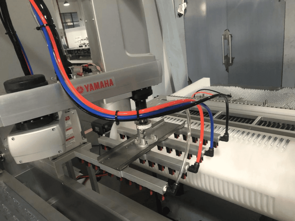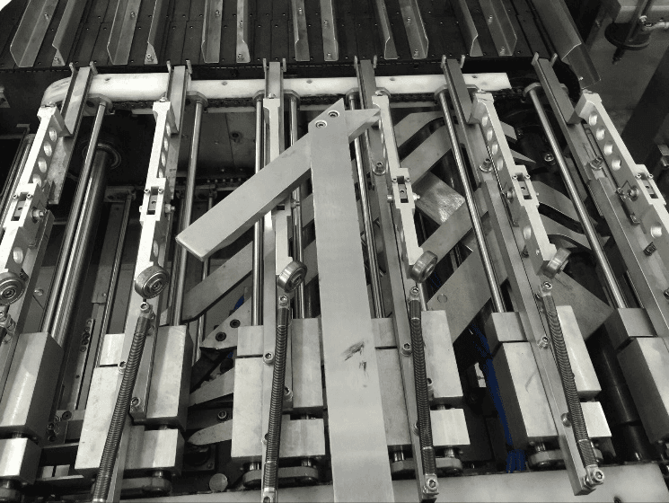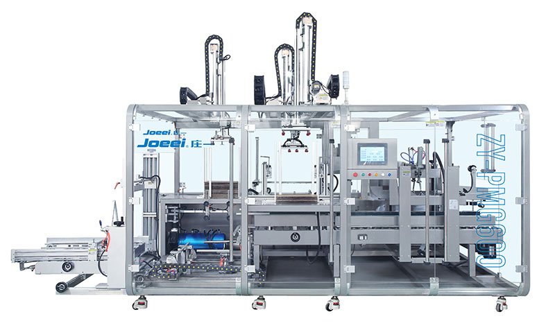
Specify blister tooling as one coordinated format system—from the product cavity and forming web to sealing, cutting, feeding and downstream transfer.
A useful tooling discussion starts with the approved pack and ends with testable acceptance evidence. It does not start with a universal material, an unverified tolerance or a promised changeover time.
What does blister pack tooling include?
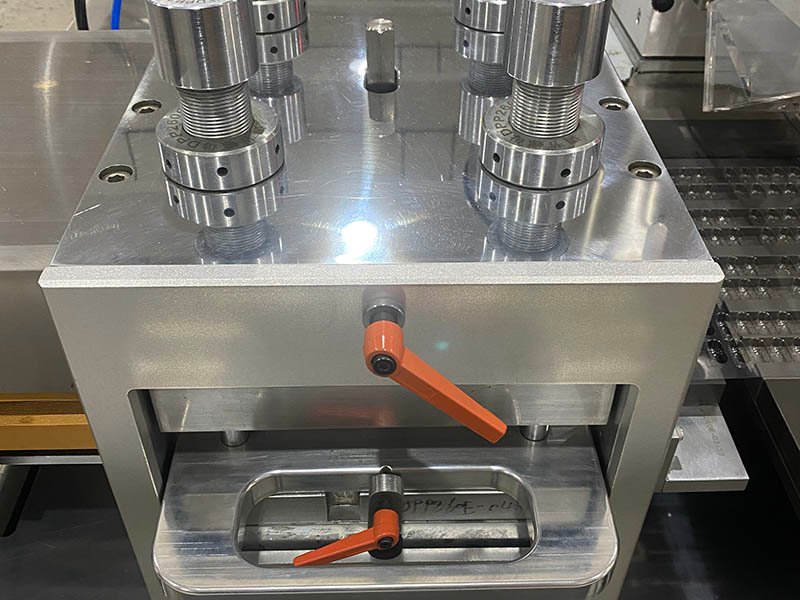
Blister pack tooling is the coordinated set of format-dependent parts that forms the cavity, presents the product, controls the sealing area, codes or perforates the web, cuts the finished card and guides it to the next operation.
The exact set depends on the machine architecture, product, forming material, lidding material, card drawing and feeder. A tooling quotation should therefore name every included component, drawing revision, material, surface requirement, spare and acceptance test—not simply say “one mold set.”
Forming
Heating plates, upper and lower forming tools, plug-assist parts, cooling and air passages create the specified cavity.
Feeding
Guides, tracks, brushes, channels or purpose-built feeders present the product without unacceptable damage or misses.
Sealing
Flat plates or rollers apply the defined pattern while the process controls temperature, pressure, dwell and registration.
Coding and perforation
Format parts locate print, embossing, score lines and perforations relative to the cavity and card.
Cutting and transfer
Punch tools, guides and discharge parts establish the finished outline and reliable handoff to collection or cartoning.
Start with the product, materials and finished blister drawing
Tooling cannot correct an undefined package. Freeze the functional requirements far enough to approve the tooling concept, while recording any development items that still need trials.
Product envelope and handling limits
Provide maximum and minimum product dimensions, not only a nominal size. Include shape, orientation, weight variation, coating, friability, tack, dust, electrostatic behavior and any surface that must not be loaded or marked.
The cavity must protect the product while supporting feeding and pack use. Excess clearance can allow movement or add headspace; insufficient clearance can interfere with loading, lidding or opening. The correct allowance is product- and material-specific.
Approved packaging system
Name the forming web, lidding material, coating or seal layer, thickness range and supplier grade. Thermoplastic and cold-form structures respond differently during forming. Material-supplier recommendations can guide a design, but they must be applied to the actual grade, geometry and process.
- Product drawing, tolerances and representative samples
- Forming and lidding structures with supplier specifications
- Cavity, seal flange, card and perforation drawing
- Opening, barrier and pack-integrity requirements
- Machine model, web direction, index and usable forming area

| Controlled input | Why tooling depends on it | Approval evidence |
|---|---|---|
| Product limits | Drive cavity envelope, orientation, feeding clearance and damage risk. | Drawing revision, tolerance range and representative samples. |
| Material structure | Affects heating, draw behavior, cooling, seal area and operating window. | Supplier grade, structure, thickness and approved specification. |
| Pack layout | Sets cavity pitch, web use, card flatness, print area and downstream presentation. | Signed blister/card drawing with machine direction. |
| Seal definition | Controls flange geometry, pattern, registration and test requirements. | Lid/base combination, opening mode and integrity method. |
| Machine interface | Limits tool envelope, mounting, services, motion and change method. | Machine serial/model data and approved interface drawing. |
| Downstream handoff | Card outline, pitch, bow and orientation affect guides and cartoner transfer. | Interface drawing and accepted-card transfer trial. |
Connect each observed pack defect to the whole process
A defect at one station does not automatically prove a tooling defect. Material variation, settings, utilities, feeder behavior, alignment, wear and downstream handling can create similar symptoms. Troubleshoot with records and controlled trials.
Incomplete or uneven cavities
Review material condition, heating, air or vacuum path, plug-assist geometry, cooling, cavity transitions and release. Use the actual web lot and the approved cavity measurement method.
Product scuffing or feeding misses
Check product variation, contact points, feeder setup, dust, static, line speed and pocket clearance. Record misses and product damage separately.
Wrinkles or channel paths
Review web tracking, lidding registration, seal-area contamination, tool parallelism and the validated temperature-pressure-dwell window. Confirm with the approved integrity test.
Weak or difficult opening
Assess the complete base/lid/coating system, seal pattern, process window, aging and opening direction. A single sealing-temperature value is not a package specification.
Rough cuts or poor card release
Inspect cutting clearance, edge condition, tool alignment, web tension and ejection. Measure the finished card against its drawing and test downstream transfer.
Drifting print or perforation
Check registration sensing, web stretch, index control, tool location and artwork tolerances. Challenge stops and restarts instead of accepting only a short uninterrupted run.
Define changeover time before anyone promises it
“Quick change” has no measurable meaning until the start point, end point, included work, operator count and acceptance conditions are written down. A credible target is demonstrated on the offered machine with the agreed tools and procedure.
State what the clock includes
- Tool cooling or safe-handling wait
- Product and material removal
- Cleaning and inspection required by procedure
- Tool and feeder replacement
- Recipe selection and permitted adjustments
- Trial packs, measurements and approval
State the test conditions
- Named source and destination formats
- Number and training level of operators
- Tools, carts, gauges and lifting aids provided
- Starting condition of the line
- Definition of an accepted first pack
- Deviation and retest rule
Design features such as accessible fasteners, positive location, keyed orientation, clear part identification and controlled recipes can reduce adjustment and error opportunity. They do not justify a universal minutes claim. Record the demonstrated result for each important format pair.
See how to calculate accepted output from cycle rate, cavities, run time and operating factor.
Specify tooling materials and surfaces by function
There is no single “GMP tooling material” that automatically suits every component. Select and document construction according to function, contact status, thermal behavior, wear, corrosion risk, cleaning method and the machine design.
Forming function
Thermal response, cooling, air paths, surface condition and release behavior matter. The correct construction and surface treatment depend on the forming material and tool design.
Sealing function
Flatness, pattern, temperature distribution, pressure application and resistance to wear or damage matter. Approve the pattern and limits against the actual material pair.
Cutting function
Edge material, hardness, clearance, alignment, serviceability and regrinding strategy affect card quality and tool life. Define wear limits instead of promising years of service.

Require a component-level schedule
For every supplied part, record the part number, function, drawing revision, construction, surface requirement, critical dimensions, inspection method and replacement status. Separate product-contact parts from non-contact structural parts and identify which certificates or reports are actually included.
Do not copy a surface-finish value, alloy, polymer grade or food-contact reference from another machine. The supplier should respond to the buyer’s intended use and documentation requirement for the actual tool.
- Materials and certificates in contractual scope
- Critical dimensions and inspection results
- Surface treatment and repair restrictions
- Wear parts, sharpening and replacement strategy
- Storage fixtures, protection and lifting method
Build maintenance around the approved tooling and site procedure
Generic online instructions cannot know the tool construction, residue, cleaning chemistry, safety risks or validated site process. The machine and tooling supplier should provide component-specific instructions; the user incorporates them into approved procedures.
Identify before removal
Confirm format number, drawing revision and installed components. Record damage or abnormal results before cleaning erases useful evidence.
Clean by approved method
Follow defined agents, tools, disassembly, exposure and drying steps. Protect sharp edges, seal faces, air ports, sensors and treated surfaces.
Inspect against limits
Check critical faces, alignment features, cutting edges, fasteners and passages using the supplier’s method and site risk assessment.
Protect and store
Use labeled fixtures or containers that prevent contact damage, corrosion, contamination and mix-ups. Control access and status.
Track history
Keep use, cleaning, inspection, repair, sharpening and replacement records where required. Link the record to a unique tool identity.
Reverify after intervention
Define the checks needed after adjustment, repair or part replacement before returning the format set to production.
Turn the tooling scope into an approval and FAT matrix
The approved drawing, quotation, component list and FAT protocol should trace to one another. This is how a buyer separates a complete format set from a vague “mold included” line item.
Send with the RFQ
- Machine model, serial number and current interface drawings
- Product drawings, tolerances and production-intent samples
- Base web, lid and coating grades with thickness ranges
- Blister/card drawing, machine direction and artwork zones
- Required accepted output and format-change definition
- Inspection, reject and downstream interface requirements
- Required drawings, reports, certificates and spare parts
Approve before manufacture
- Tooling list with part numbers and revision control
- Cavity, seal, cut, perforation and coding geometry
- Construction, surface and critical dimensional requirements
- Mounting, utility and safety interfaces
- Feeder and product-contact boundary
- Changeover procedure, tools and operator assumptions
- FAT samples, methods, quantities and acceptance criteria
| Acceptance topic | Challenge or check | Evidence to retain | Ambiguity to remove |
|---|---|---|---|
| Tool identity | Match installed parts to the approved format list and drawings. | Part numbers, revisions, photographs and inspection status. | “Complete set” without an itemized list. |
| Forming | Run the approved material range and measure defined cavity features. | Settings, material lots, samples and dimensional results. | Appearance-only approval. |
| Feeding | Use production-intent product variation at the agreed rate and duration. | Misses, damage, interventions, stops and accepted output. | Hand-selected products in a short demonstration. |
| Sealing | Challenge the agreed operating window and stop/restart conditions. | Parameter records and results from the approved seal/integrity method. | “Perfect seal” without a test and limit. |
| Cut and handoff | Measure card geometry and run the intended discharge or cartoner transfer. | Dimensions, edge/perforation results and transfer observations. | Accepting loose samples without the interface. |
| Changeover | Execute the named format pair with agreed operators and included work. | Start/end definition, time, steps, adjustments and first accepted pack. | A headline time without test conditions. |
Five tooling claims that need evidence
“One mold fits all”
Ask which product, cavity, material and card variations are covered and what compromises were accepted.
“Perfect sealing”
Ask for the material pair, operating window, sample plan, test method and acceptance limit.
“Micron precision”
Ask which dimensions have that tolerance, why it matters and how inspection is performed.
“Fast changeover”
Ask for the format pair, included steps, operators, starting condition and first-good-pack definition.
“GMP tooling”
Ask for the intended-use response, documented construction, cleanability, records and validation responsibilities.
Blister pack tooling FAQ
What is blister pack tooling?
What information is needed to design blister tooling?
Is one forming mold suitable for several tablet or capsule sizes?
How fast should a blister machine format change be?
Which materials should blister tooling use?
Does precision tooling guarantee blister seal integrity?
What tooling should be tested during FAT?
How should blister tooling be maintained and stored?
Turn your blister drawing into a testable tooling scope
Send the product drawing and samples, material structures, blister/card layout, machine model, target accepted output and changeover definition. HIJ can review the format boundary and identify the drawings, tooling components and FAT evidence that belong in the proposal.
Technical basis
- 21 CFR 211.63 — Equipment design, size and location
- 21 CFR 211.67 — Equipment cleaning and maintenance
- European Commission — EudraLex Volume 4 GMP guidance
- Honeywell — Aclar Films Tooling Design Best Practices (material-specific guidance; apply only to the stated film and verified project conditions).