Troubleshooting guide · operator, maintenance and quality evidence
Troubleshoot a blister packaging machine by preserving the alarm and affected packs, checking the last controlled change, and locating the first station where the process became abnormal. Do not raise temperature, pressure or speed until the material, utilities, tooling and approved recipe have been checked.
Use one rule throughout the investigation: change one authorized variable, test against a defined acceptance criterion, and restore the approved baseline if the result is unclear.
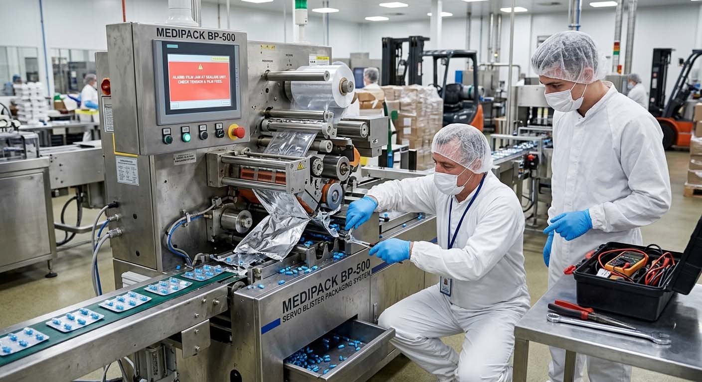
Use this safe sequence before changing a setpoint
- Contain the affected product. Mark the last known good pack, segregate suspect output and notify production or quality through the approved deviation process.
- Preserve what the machine already knows. Record the exact HMI alarm, timestamp, mode, active recipe, batch, material lots, tooling revision and station state before a reset erases context.
- Review the last controlled change. Check the latest format change, film or foil lot, product batch, cleaning, maintenance, software revision, utility interruption and operator handover.
- Verify utilities and actual values. Compare available electrical supply, compressed air, vacuum, cooling water and measured process values with the model-specific manual and approved setup.
- Find the earliest abnormal event. Separate forming, feeding, sealing, transport, cutting, inspection and controls. A cutter jam may be the final consequence of an earlier registration drift.
- Test one authorized change. Stay inside the approved operating range, use a defined challenge sample and record the result. Restore baseline before testing another cause.
- Release with evidence. Confirm pack quality, alarm clearance, guarding, reject function, documentation and required quality approval before production resumes.
Blister packaging machine troubleshooting matrix: 10 common faults
The matrix below is a first-response map. It identifies the evidence to collect and the subsystem to investigate; it does not replace the applicable HIJ manual, an approved recipe or a site investigation.
| Symptom | Check first | Useful evidence | Stop or escalate when |
|---|---|---|---|
| 1. Weak, open or inconsistent seals | Material identity and orientation, contamination, contact pattern, actual temperature, pressure and dwell | Defect map by lane, retained material lots, recipe and approved seal test | The defect repeats after verified cleaning, material and baseline checks |
| 2. Foil wrinkles or channel leaks | Foil path, web tension, registration, sealing-face condition and pressure distribution | Wrinkle direction, edge position and lane-specific samples | Tooling damage, repeated lane failure or seal integrity cannot be demonstrated |
| 3. Shallow or uneven pockets | Forming web lot, heating uniformity, air or vacuum path, mold seating and cooling | Pocket measurements and defect location across the web | Pocket geometry remains outside the approved drawing |
| 4. Torn film or excessive thinning | Material grade, heat distribution, cavity geometry, web drag and forming pressure or vacuum | Film lot, tear location, pocket depth and previous stable setup | Product protection or pack integrity is uncertain |
| 5. Empty cavities or double fills | Product flow, dust, bridging, feeder contact, timing and cavity alignment | Missing-position pattern, feeder video and rejected-pack images | Inspection cannot contain the defect or the cause begins upstream |
| 6. Chipped tablets or damaged capsules | Product condition, drop height, contact surfaces, feeder wear and cavity fit | Damage location before and after feeding plus representative product samples | Product quality limits or containment are uncertain |
| 7. Web wandering or registration drift | Roll loading, guides, unwind brake, tension, sensor response and roller cleanliness | Edge position from unwind to cutting and mark-sensor history | Tracking cannot remain stable at the approved baseline speed |
| 8. Off-center cutting or punch jam | Upstream registration, trim path, tooling seating, wear, fasteners and foreign material | Cut-position samples, overload history and installed tooling list | Tooling is damaged, overload repeats or guarded access is required |
| 9. PLC, servo or sensor alarm | Exact alarm history, permissives, interlocks, sensor state, feedback and recent changes | Timestamp, cycle position, recipe, input state and repeated sequence | Safety logic, program, drive parameter or electrical testing needs authorized access |
| 10. Vision rejects good packs or misses defects | Saved images, lighting, lens, trigger timing, product position, recipe and challenge set | Accepted and rejected images with reference samples | True defects may escape or reject segregation cannot be verified |
Weak seals, open seals, wrinkles and channel leaks
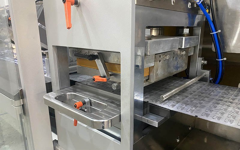
A sealing problem is not automatically a heater problem. First map the defect. A full-width failure suggests a shared material, process or utility condition. A repeated lane or edge pattern points more strongly to local contamination, alignment, pressure distribution or tooling condition.
Check material and contact first
- Confirm forming web and lidding foil identity, orientation, coating, lot and approved supplier record.
- After safe isolation, inspect the approved cleaning status, residue, damage and sealing-face contact pattern.
- Retain both failed and acceptable samples from the same run.
Then compare the process window
- Compare displayed and independently verified values where the SOP requires it.
- Review dwell, line speed, pressure contact and cooling against the approved recipe.
- Use the site’s approved integrity or peel evaluation; visual appearance alone is not release evidence.
A higher temperature can hide another cause and may damage the web, coating or product. If a material or coating changed, resolve that compatibility question before rewriting the machine recipe. The blister packaging materials guide helps separate material selection from machine adjustment.
Shallow pockets, thinning, tears and uneven forming
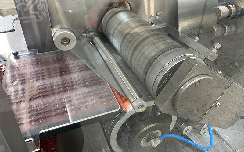
Begin with the pattern, not the setpoint. If all cavities are affected across the web, investigate shared material, heating, utility and process conditions. If one lane, corner or repeated pocket is affected, investigate a local heater zone, blocked path, mold feature, guide or alignment condition.
- Verify film grade, thickness, storage and acclimatization against the approved material record.
- Check the web path for drag, edge damage or contamination before the film reaches the forming station.
- Compare actual heating behavior with the model-specific setup using the approved measurement method.
- Inspect applicable air, vacuum and cooling paths for restriction or leakage after safe isolation.
- Confirm mold seating, change-part identity and the approved cavity drawing after a format change.
Keep a cavity-position map, pocket measurements, material lot, recipe version and samples from before and after the authorized adjustment. A pocket that looks acceptable but misses the drawing or protection requirement is not a demonstrated fix.
Empty cavities, double fills and product damage

Record the spatial pattern before touching the feeder. A consistent missing lane deserves a different investigation from random empty cavities. Compare product geometry, dust load, surface condition and the current batch with the last stable batch; a changed product can create a packaging symptom even when the machine has not changed.
- Repeated lane or position: check cavity alignment, local feeder contact, track wear and installed change parts.
- Random misses: check hopper flow, bridging, vibration, dust, intermittent timing and upstream product condition.
- Chipping or capsule damage: compare damage before and after feeding, then check contact points, drop height, speed relationship and cavity fit.
- Double fills: verify feeder control and inspection challenge evidence; do not weaken the reject limit to keep the line running.
Web tracking, registration, cutting and waste-strip faults

The final off-center cut is often not the first failure. Trace the web in process order:
- Confirm the roll is centered and loaded according to the machine procedure.
- Inspect guides, rollers and sensors for contamination, damage and correct seating.
- Observe unwind brake or tension behavior during acceleration, steady running and deceleration.
- Confirm registration-mark quality and sensor response using the approved material.
- Only after upstream registration is stable, inspect cutting-tool seating, wear, trim path and waste take-up.
If the fault begins after changeover, compare installed parts and recorded settings with the approved format list. Do not compensate for a mechanical mismatch with a large electronic offset. Stop if the punch overloads, tooling is damaged or waste enters a guarded danger zone.
PLC, HMI, servo, sensor and vision-inspection faults

A servo following alarm can be caused by mechanical resistance. A sensor timeout can follow a web-position problem. An interlock may be functioning correctly because another station never reached its permissive state. Before reset, retain the exact alarm, machine state, active recipe, cycle position and whether the event repeats at the same point.
- Compare input and output states only when the technician is authorized and the machine is in the approved diagnostic mode.
- Inspect connectors, cables and sensor surfaces only after the required energy-control procedure is applied.
- Review program, HMI recipe, drive parameter, network and inspection-software changes through change control.
- Never bypass a safety circuit or alter validated logic as a troubleshooting shortcut.

When good packs are rejected intermittently, check lens cleanliness, lighting, trigger timing, product position and recipe selection before changing sensitivity. Use a controlled challenge set to show that required defects are still detected and segregated. The blister machine vision inspection guide explains how to define that evidence in the URS and FAT.
What to send the OEM or service engineer
A complete first message shortens diagnosis and helps the supplier distinguish a product, material, tooling, utility, control or mechanical cause. Remove or protect confidential production data according to site policy.
Fault evidence package
- Machine model, serial number and current software or recipe version
- Exact alarm code, timestamp, mode and alarm-history export or photograph
- Product and format identification plus forming-web and lidding-foil lots
- Approved setpoints and actual values from the specified measurement method
- Photos of the defect, web path and relevant station after safe isolation
- A short sequence video if permitted by site safety and confidentiality rules
- The last controlled change and every action already attempted, in order
- Suspect quantity, containment status and the quality decision still required
Stop local troubleshooting and escalate when the safety circuit is involved, guarded access or hazardous-energy work is required, tooling is damaged, product containment is uncertain, the defect cannot be reliably detected, or the approved process window cannot hold specification.
Prevent the same fault from returning
A corrective action is stronger when it removes the verified cause and leaves a control that can detect recurrence. Link the finding to the maintenance plan, spare-parts list, operator check, alarm matrix, training record, cleaning procedure or change-control process that failed to prevent it. For drug-product packing equipment, 21 CFR 211.67 addresses cleaning, maintenance, written procedures and related records.
Keep the failure pattern, test method, result and approval together. If the fault reveals a design limitation, add it to the next URS or FAT challenge rather than relying on operator memory.
Frequently asked questions
Why is a blister packaging machine not sealing properly when the setpoint looks correct?
The displayed setpoint does not prove material identity, foil orientation, coating condition, contact pressure, dwell or the actual seal-interface temperature. Confirm the material and cleaning status, compare actual values with the approved recipe and evaluate retained packs with the site’s approved seal test.
What causes random empty blister cavities?
Random misses can result from unstable product flow, bridging, dust, vibration, timing or intermittent upstream conditions. A repeated lane or position points more strongly to geometry, feeder wear or alignment. Record the pattern before adjusting the feeder.
How should shallow or torn blister pockets be investigated?
Map the defect across the web, confirm the film lot and last controlled change, then check the web path, heating behavior, applicable air or vacuum path, cooling and mold seating against the approved setup. Retain measured pocket samples before and after one authorized change.
Why does blister registration drift only after the machine speeds up?
Acceleration can reveal unwind-brake, tension, guide, roller, sensor or web-quality behavior that is not visible during slow jogging. Follow the web from unwind to cutting and identify the first point where edge position or mark relationship changes.
What does an intermittent PLC, servo or sensor alarm mean?
It means the control system detected a condition outside its logic or timing, but the named device may not be the root cause. Preserve the alarm history and cycle position, then review permissives, feedback, connections, contamination, mechanical resistance and recent controlled changes.
Should inspection sensitivity be reduced when good blisters are rejected?
Not as the first response. Save accepted and rejected images, confirm lighting, lens condition, trigger timing, product position and the active recipe, then repeat the approved challenge set. Any change must still demonstrate required defect detection and reject segregation.
When should maintenance stop troubleshooting and contact the OEM?
Escalate when safety functions, guarded access, hazardous energy, damaged tooling, repeated overloads, software logic, uncertain product containment or an unstable approved process are involved. Send the OEM the complete evidence package rather than only the visible symptom.
What troubleshooting functions should be challenged during FAT?
Challenge alarm history, station-level diagnostics, sensor-state visibility, recipe access, changeover verification, reject handling and safe recovery from representative faults. Define prerequisites, expected results, acceptance criteria, retained data and responsibility for open actions before execution.
Primary regulatory and technical references
- 29 CFR 1910.147 — control of hazardous energy (lockout/tagout)
- 21 CFR 211.67 — equipment cleaning and maintenance
- European Commission EudraLex Volume 4 — Annex 15 qualification and validation
Machine-specific limits, access rules and recovery procedures must come from the applicable machine manual, approved customer documents, site SOP and validated production recipe.
Send HIJ the fault evidence—not only the symptom
Share the machine model, alarm history, product and material data, defect pattern and actions already attempted. HIJ can review the evidence and define the next safe diagnostic question or the requirements for a replacement machine.