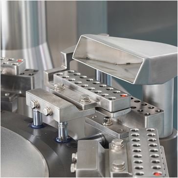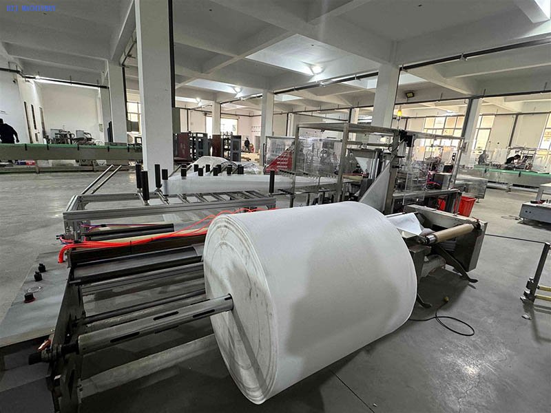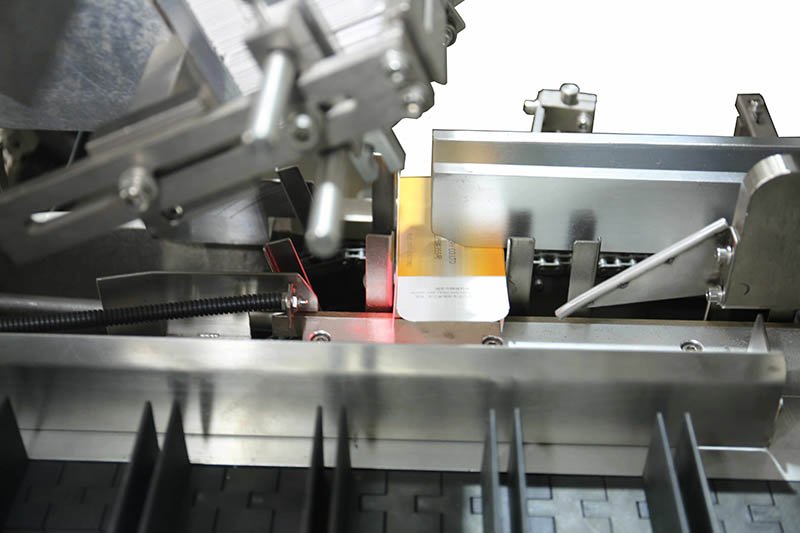
Assembly identification · Liquid filling equipment
Filling machine parts include the product supply, metering assembly, fluid connections and filling nozzle, supported by container tooling, drives and controls. Identify the configured assembly before ordering a replacement.
- 1. Product supplyVessel and feed connections
- 2. Metering assemblyThe specified pump or dosing mechanism
- 3. Dispensing pointNozzle and container interface
Functional illustration, not a machine drawing or universal bill of materials. Valves, manifolds and other interfaces depend on the configured system.
Main filling machine parts and what they do
Start by separating the liquid path from the mechanisms that position, close and inspect the container. A nozzle problem, a container-positioning problem and a closure problem may interrupt the same machine, but they call for different drawings and replacement parts.
| Assembly | Function | What must match |
|---|---|---|
| Product vessel and feed connection | Present product to the filling system in its required condition. | Connection geometry, product-contact materials, operating conditions and any specified level or agitation arrangement. |
| Metering pump or dosing assembly | Deliver product through the configured metering sequence. | Pump identification, working range, assembly revision, drive interface and complete approved product path. |
| Tubing, hoses, fittings and applicable valves | Connect and control the configured fluid route. | Material, dimensions, connection type, valve orientation and required cleaning or replacement method. |
| Filling nozzle and its mounting | Present the discharge point to the container opening. | Nozzle geometry, connection, mounting, travel and clearance for the actual container. |
| Container guides, fixtures and format tooling | Locate and transfer the syringe, tube or other specified container. | Container drawing, tooling set, filling position and interfaces with adjacent stations. |
| Drive, sensing and control components | Coordinate motion and respond to the configured detection signals. | Exact device code, electrical and mechanical interfaces, configuration and safety requirements. |
Depending on the design, a seal may belong inside a pump, valve, connection or closure station. “Filling machine seal” is therefore not a complete part description. Likewise, a bottle filling machine parts list cannot establish compatibility with a plastic syringe filler, a tube filler or a roll-fed unit-dose system.
This guide concerns liquid and semi-solid filling assemblies. For hard-capsule powder handling and tooling, use the separate capsule filling machine parts guide.
Identify the filling pump before choosing its spare parts
The word “pump” does not identify the replacement assembly. HIJ's equipment references illustrate three relevant configurations; they do not establish a common spare-parts catalogue across the machines.
Ceramic plunger assemblies: plastic syringe reference
The HIJ-DZA200 documentation identifies a ceramic plunger pump for plastic syringe filling and separately lists a ceramic valve assembly associated with filling-volume requirements. It also notes that a substantial change in filling range can require a different pump.
Record the pump and valve references, the installed head and the intended fill range. Confirm whether the supplier specifies a matched assembly and what that assembly includes. Do not order a loose internal component by appearance if the approved replacement is a complete or matched set. For the corresponding platform, see the prefilled syringe filling equipment range.
Mechanical piston filling: tube reference
The TF-60 reference describes mechanical-piston filling as part of its tube filling and sealing sequence. Identify the metering arrangement and the installed nozzle separately from the tube holder, registration components and tail-closing tools.
A new tube diameter can affect format tooling even when the product formulation stays the same. Conversely, changing the filling assembly does not establish that the existing tube-closing setup is suitable. The tube filling machine parts guide covers the wider tube-specific station and tooling distinctions.
Peristaltic and other product-dependent pumps: unit-dose reference
The GGS-118P5 documentation describes product-dependent pump selection and includes a peristaltic-pump reference. With a peristaltic pump, the pump tubing is a product-contact and wearing element; its identity matters as well as the pumphead and drive.
Williamson's peristaltic-pump explanation describes fluid contact with the tubing and the factors affecting tubing life. This supports checking the specified tubing rather than treating any flexible hose as equivalent. It is not evidence that a Williamson pump is fitted to HIJ equipment or that one replacement interval suits every formulation.
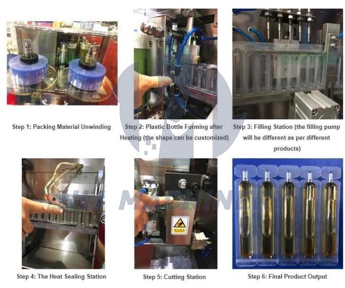
Use the plastic ampoule and oral-liquid filling/sealing platform for the machine context. A forming mould, a sealing tool and a metering pump serve different jobs, even when all appear on the same quotation.
Nozzles, connections and seals need more than a visual match
A filling nozzle must connect to the product path and work at the container interface. Its mounting and movement need to match the machine, while its outlet geometry must be reviewed against the actual opening and proposed filling conditions. A similar outside diameter alone is not sufficient identification.
Ask whether the proposed nozzle is a fixed dispensing tip or part of an actuated shut-off arrangement. Where a shut-off function exists, establish which actuator, valve element, seal and control interface belong to the assembly. Do not assume every nozzle contains an anti-drip valve or that a generic tip provides the same behaviour.
For seals and tubing, document the specified material and dimensions, product exposure, cleaning conditions and any required traceability. A colour, a photograph or the phrase “food grade” does not establish the exact material identity. Compatibility also has to account for the cleaning process, not just the product during filling.
Keep the replacement boundary explicit. Ask whether the quotation covers the nozzle alone, a complete valve/nozzle assembly, the associated seals, fittings and mounting hardware, or an installed and tested change. Otherwise two quotations with the same part name may cover different scopes.
Separate wearing parts, format parts and control components
Wearing parts are managed according to their specified service conditions and observed condition. Format parts are selected for a product or container presentation. Control components have electrical, software and functional interfaces. These categories can overlap, but they should not be mixed into one unidentified “spares kit”.
The DZA200 reference states that different syringe specifications need different moulds and describes syringe and cap feeding arrangements. The TF-60 reference similarly identifies mould changes for different tube diameters. Neither statement means that only one component changes for every possible format transition: the approved format matrix must define the complete set.
A sensor replacement also needs more than a matching connector. Confirm the complete order code, supply and output requirements, sensing arrangement, mounting and required settings. A PLC or drive replacement may additionally require a compatible project, parameters and an authorised restoration method. Do not change an interlock or safety function to make a substitute component run.
How to identify compatible filling machine spare parts
- Locate the machine and assembly. Record the machine model and serial number, the station and the installed filling-head position. State any known modification since the original build.
- Find the drawing reference. Use the assembly drawing, item number and revision where available. Distinguish an installed part marking from a supplier quotation reference.
- Record the actual installed identification. Photograph the marking and the surrounding assembly. Use an authorised inspection method; isolate hazardous energy before any access that requires it.
- Define the operating and format context. Identify the product, fill range, container, cleaning conditions and relevant tooling revision without sending confidential formulation details through an unsuitable channel.
- Get the replacement boundary in writing. Confirm included companion items, compatibility basis, documentation and whether the supplier requires a matched set or an updated assembly.
- Agree the verification after installation. State who installs, checks and releases the equipment, and what evidence is needed before routine production resumes.
If the part number or drawing is missing, say so. An overview image and close-up can start identification, but they cannot by themselves prove material, internal geometry or revision. Do not assign an invented part number to make the request appear complete.
For an equipment purchase rather than a replacement request, begin with the pharmaceutical filling machine selection guide; the appropriate route should be established before selecting its component list.
Record the symptom before deciding which part has failed
A low fill, a drip or an intermittent stop is an observation, not a confirmed component diagnosis. The following records can help the responsible engineer distinguish a part fault from a feed, format, measurement or configuration problem.
| Observed issue | Useful evidence for the review |
|---|---|
| Individual fills outside the agreed range | Results by filling position, measurement method, product condition, start-up or steady-run timing and recent changes. |
| Dripping at the dispensing point | The exact location and timing, installed nozzle/valve identification, operating conditions and any recent cleaning or assembly work. |
| Container interference or poor alignment | Container and tooling references, the affected station, format settings and a safely obtained overview of the interface. |
| Intermittent detection or sequence stops | Alarm records, affected input or station, device identification and the sequence immediately before the stop. |
Follow the site's approved response to suspected product-quality or safety problems. Stop and escalate where required; do not bypass guards, reach into a running mechanism, repeatedly reset a safety trip or experiment with unapproved cleaning chemicals to identify a fault.
Verify the assembled system before returning it to production
Receiving inspection should reconcile the delivered identification, quantity, drawing revision, companion items and documentation with the approved order. Protect product-contact components from damage and contamination during storage and handling, using their specified packaging and storage conditions.
After authorised installation, the release checks should address the affected functions: correct assembly and connections, cleanliness, leaks, motion and clearance, applicable detection/interlocks, and filling results under defined conditions. A part fitting physically is not evidence that the original process performance has been restored.
For drug manufacturing, 21 CFR 211.65 addresses product-contact construction and possible contamination from operating substances. 21 CFR 211.67 addresses equipment cleaning, maintenance, procedures and records. These references do not certify a replacement component or replace the site's quality assessment.
The responsible team should decide whether a like-for-like replacement, material change, revised pump, nozzle geometry or control-component change affects the approved process or qualification status. Keep the part identity, reason for replacement, installation record, test results and release decision together.
Questions about filling machine replacement parts
Are filling machine parts universal across models?
No. Similar names or appearances do not establish matching geometry, product-contact materials, working range, interfaces or revision. Identify the installed assembly and obtain a compatibility basis for the proposed replacement.
Does an inaccurate fill mean the pump must be replaced?
Not necessarily. Record the results, measurement method, affected filling position, product and operating conditions before diagnosing the fault. Feeding, container handling, settings and other parts of the system may need review alongside the pump.
Is a nozzle set the same as one spare nozzle?
Not automatically. A set may cover one filling position, one machine or multiple positions. Specify the number and identity of the positions and the complete contents of the set before ordering.
Does a stainless-steel grade prove compatibility?
No. The complete component, seals, connections, surface condition, product exposure and cleaning conditions need assessment. A material-grade label alone does not establish fit, suitability, cleanability or a sterile process.
Can a third-party pump or sensor be substituted?
Only after the proposed substitute has been reviewed against the relevant mechanical, electrical, material, control and safety interfaces. Confirm any effect on the approved process, documentation and qualification. A matching size or connector is not enough.
How should a minimum spare-parts stock be chosen?
Use the installed assembly list, failure and replacement history, criticality, confirmed replenishment conditions, storage requirements and approved maintenance plan. Separate planned replacement demand from contingency stock; there is no universal stock quantity or replacement interval for every filler.
Discuss the filling assembly you need to identify
Send the machine model and serial number, assembly or part marking, relevant format and clear photographs. State whether you need a like-for-like spare, a complete filling-path assembly or tooling for a different container.
HIJ can review the request against the relevant equipment information and identify what still needs confirmation before a quotation. Availability, compatibility and the supplied scope must be confirmed for the specific request.
Discuss a Filling Assembly