Connected equipment · Accepted-unit output
A liquid filling line connects product and container handling, filling, closing and specified downstream operations. Its useful output depends on the complete process boundary and the handovers between stations.
- Prepare and presentProduct and container supply
- Fill and closeMetering and primary closure
- Verify and transferChecks and the agreed handoff
Illustrative scope map. Equipment boundaries depend on the container, product and closing process.
Start with the containers entering and leaving each operation
Define the product, container, closure and required finished condition before listing machines. A preformed plastic syringe, an empty tube and a container formed from packaging web create different filling-line requirements. Not every project needs a bottle washer, bottle unscrambler or a separate capper.
| Scope area | What the project must define | Why it matters |
|---|---|---|
| Product supply | The formulation's filling condition, supply arrangement, replenishment and product-contact boundary. | The filling platform cannot be assessed independently of the material it receives. |
| Container presentation | Preformed or formed in-machine; loose, oriented, in a fixture or in another specified presentation. | It establishes the incoming handling and format-tooling requirement. |
| Filling and primary closing | Metering, fill target, closure operation and the required final primary-pack condition. | These functions may share one machine, but each needs a defined acceptance basis. |
| Verification and disposition | Included checks, rejected-unit routing, reconciliation and the response when a check cannot be completed. | A detection signal alone does not establish that the affected unit was correctly handled. |
| Downstream packaging | Labelling, grouping, cartoning or another agreed handoff, with responsibilities identified. | The accepted finished-output boundary determines the relevant line rate. |
Record which functions are already installed, included in the supply, supplied by another vendor or retained as a site activity. This turns a list of filling line equipment into an understandable project scope.
Cosmetic bottle and jar projects can use the existing automatic cosmetic filling line page for the commercial configuration discussion. This guide concentrates on integration decisions across documented filling routes, rather than replacing that product page.
Three documented routes have different line boundaries
Plastic syringes: filling and capping with defined downstream equipment
The HIJ-DZA200 reference describes plastic syringe filling and capping. It also describes standalone use or connection with ancillary equipment such as assembly and labelling machines. This supports a configurable line discussion, not an assertion that every listed module is included in every quotation.
Identify the syringe presentation and the condition expected at each transfer. The prefilled syringe equipment range provides the relevant platform context; the actual product, closure and inspection scope still determine the project.
Tubes: several primary-pack operations on one platform
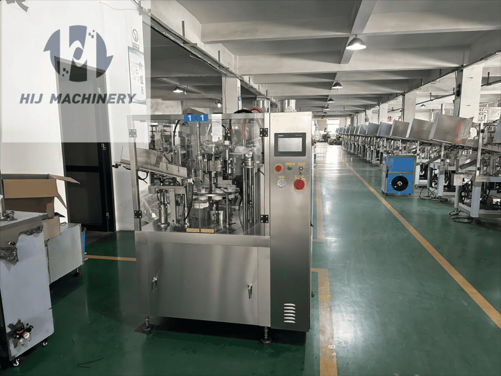
The TF-60 reference combines tube feeding, mechanical-piston filling, heating and sealing functions. Its discharge therefore concerns the specified filled and closed tube, while labelling or cartoning can be a separate downstream requirement.
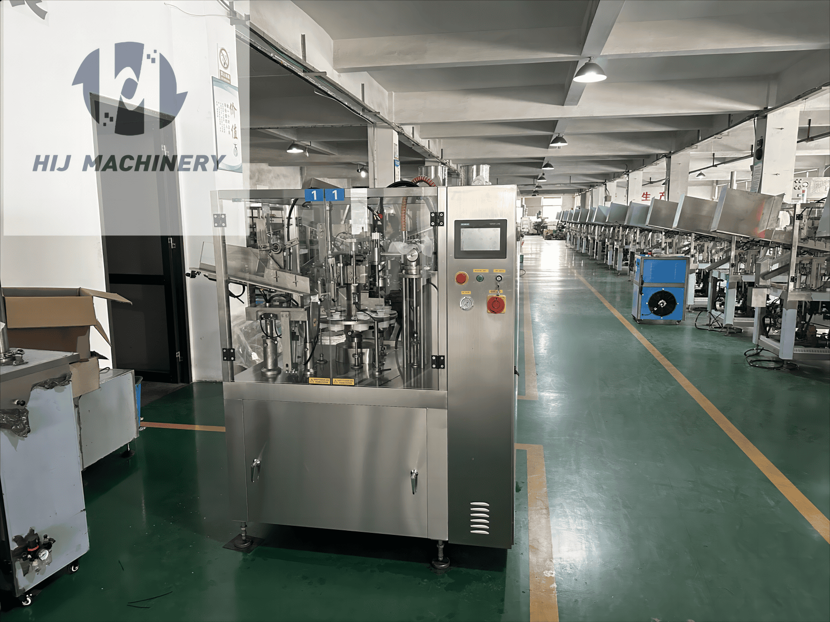
For tube-specific access and utility planning, use the tube filling line layout guide. A general integration diagram cannot establish a room's usable floor area or a machine's service clearances.
Plastic unit-dose packs: forming is part of the primary process
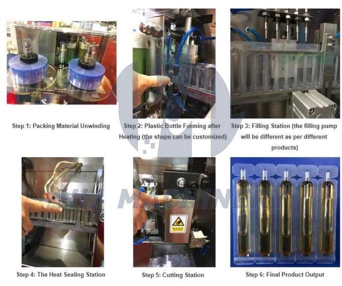
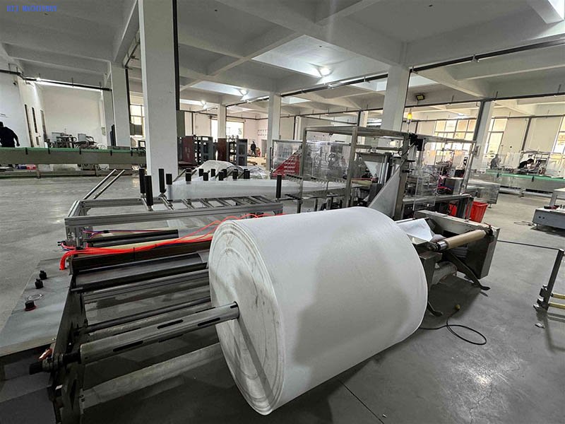
The GGS-118P5 reference describes web unwinding, forming, filling, sealing and separation, and mentions connection with labelling equipment. Pump selection is product-dependent. This is a different starting point from presenting preformed bottles to a filler and capper.
Review the plastic unit-dose filling and sealing platform against the intended product and pack. Do not treat its formed-container route as evidence of extrusion BFS or a sterile-vial filling system.
Use an interface matrix before approving the line layout
For every handover, state what moves, how it is presented, who owns the transfer hardware and which conditions permit movement. Keep the mechanical, control and quality responsibilities together so that an unresolved boundary cannot disappear between suppliers.
| Interface | Definition to agree | Trial or document evidence |
|---|---|---|
| Physical transfer | Container state, orientation, pitch where relevant, support surfaces, transfer height and tolerance. | Approved drawings and representative transfers with the agreed difficult formats. |
| Ready and permitted-to-run states | Which equipment reports availability, which equipment acts on it and what happens if the signal is lost. | A reviewed signal list and an observed start, hold and restart sequence. |
| Downstream blockage | Detection point, permitted accumulation and the agreed upstream response. | A controlled blockage challenge, including recovery and the disposition of affected units. |
| Reject and inspection status | How an inspection result stays associated with the correct unit or group through the handoff. | Known challenge samples, physical routing and reconciliation. |
| Changeover and job data | Format identity, recipe ownership, code data and authorised changes across the connected equipment. | A documented format change and checks of the resulting settings and first-off output. |
A shared PLC brand or a conveyor between machines does not resolve these interfaces. The integrator should identify the implementation, responsibilities and tests in the contracted scope. Safety-related interfaces must be designed and reviewed by the responsible specialists; do not bypass a guard or interlock to achieve continuity.
Balance the line with accepted-unit rates and a defined buffer strategy
Compare station capacities in compatible units and under the same product, format and test conditions. A filling stroke, accepted closed container and accepted carton are different measures. Include the containers per carton when converting downstream capacity.
The slowest demonstrated step or unstable handover can limit the connected process. Faster upstream equipment may create accumulation rather than additional accepted finished output. Record sustained results over a defined run instead of combining unrelated catalogue maxima.
Specify where accumulation is allowed and the condition of the container at that point. Open product, an unfinished closure and a closed pack may have very different restrictions. Do not apply the numerical example to a protected filling zone without the responsible process assessment.
A buffer can absorb a defined interruption; it cannot make an indefinitely slower downstream operation keep up. The acceptance plan should include both short interruptions and sustained operation.
Resolve access, utilities and replenishment before fixing the footprint
A machine envelope is only one part of the layout. Include operator positions, material replenishment, product-contact part removal, cleaning access, electrical and pneumatic access, reject handling and safe maintenance routes.
Record utility requirements at the agreed supply boundary: available service, required connection, operating condition and responsibility for installation. Where equipment has simultaneous demand or supporting units, include those in the review rather than sizing the supply from one machine label alone.
Show how product and packaging components reach the line and how finished and rejected units leave it. A layout that fits the equipment but blocks replenishment or cleaning can introduce avoidable stops. Confirm the working arrangement with the intended operators and maintenance team.
For a broader integration discussion, use the integrated packaging project scope. Actual drawings and responsibilities remain project-specific; a generic drawing is not a site installation approval.
Define controls, records and sterile-process requirements separately
The line specification should identify the controlled functions, authorised settings, alarm information, records and recovery decisions needed for the intended process. Explain how job data and rejected units are reconciled after a stop or format change.
For drug manufacturing, 21 CFR 211.68 addresses automatic, mechanical and electronic equipment, including checking and control requirements. It is a reference for the site's assessment, not a certificate supplied by naming a PLC or HMI.
If the product requires aseptic processing, define that requirement at the beginning. The FDA aseptic-processing guidance concerns sterile drug and biological manufacture. A connected machine sequence, stainless-steel enclosure or workshop photograph does not establish the required sterile-process design or qualification.
Test the connected sequence, including stops and recovery
Individual machine tests are useful, but the integration review also needs evidence at the interfaces. Agree the formats, product or representative test material, operating boundary and acceptance criteria before the run.
- Start-up and steady operation. Observe container presentation, filling/closing, checks and transfers over the defined elapsed run. Record accepted output, rejected units and stops.
- Supply interruption. Challenge a defined shortage of containers, product or packaging components using the approved method. Check the intended hold, recovery and first-off disposition.
- Downstream blockage. Verify the specified accumulation or stop response and the handling of units already between stations.
- Inspection and reject functions. Use identified challenge samples to show detection, correct physical disposition and reconciliation.
- Format change. Verify the agreed tooling, settings, data and release checks across the complete affected sequence.
- Restart and abnormal-state recovery. Observe only the approved challenges and recovery procedures. Keep safety tests under qualified control and document unresolved deviations.
Retain the actual conditions and results, not only a summary saying “line tested”. Identify which checks remain site-dependent and who closes the open actions before routine production.
What belongs in a complete filling-line quotation?
Separate the filling platform from container feed, closing, inspection, transfers, accumulation, downstream packaging, format parts, controls and documentation. Mark each item as included, optional, supplied by another party or outside scope.
Ask who acts as line integrator and who owns each interface, including the response if a supplied module cannot achieve the agreed handover. State the accepted-output basis and the evidence required for acceptance.
A proposal described as a complete filling line should still identify its limits. Room works, utilities, product preparation, environmental controls, site qualification and continuing maintenance are not automatically included in that phrase. Comparable scopes matter more than an unexplained machine total.
Questions about liquid filling line integration
What is the difference between a filling machine and a filling line?
A filling machine performs its configured operations on one platform. A filling line covers the defined connected sequence, including supply, transfers, closing and downstream tasks where specified. Integration and acceptance depend on the complete boundary, not the number of machines alone.
Does an automatic filling line always need separate machines for each step?
No. Several operations may share a platform, such as filling and tube sealing or web forming, filling and sealing. Define the required functions and interfaces before deciding how many machines are needed.
Will a faster filler increase the complete line's output?
Only if the rest of the configured process can sustain the required handovers and accepted output. A downstream bottleneck, unstable feeding, rejects or repeated stops can limit the result even when the filler has spare nominal capacity.
Should every liquid filling line have an accumulation conveyor?
No. The permitted holding condition, container state, available space and interruption strategy must determine the design. Where accumulation is unsuitable, define the appropriate upstream hold or stop response instead.
Can existing downstream equipment be integrated?
Potentially, after reviewing the actual mechanical, control, safety, product and data interfaces. Confirm usable capacity and format limits through an agreed assessment; a matching conveyor height alone does not approve the connection.
What information is needed to begin a line review?
Provide the product profile, container and closure drawings, format matrix, required accepted output and current equipment list. Add a dimensioned site layout, available utilities, downstream scope and any sterile-process or documentation requirements.
Define the filling route and the handovers you need
Send the product and pack, required accepted output, existing equipment and a layout showing the planned interfaces. Identify which operations the enquiry must include and which equipment or site work is already available.
HIJ can review the relevant documented equipment route and integration scope. Request a proposal with clear handover, control, test and supply responsibilities rather than assuming that every operation is included.
Discuss My Filling Line