Site planning · Tube filling · Utilities
A tube filling line layout needs room for the machine, operators, replenishment, cleaning, maintenance and auxiliary equipment. Machine footprint alone is not the required production-room area.
The TF-60 reference document makes that difference visible: about 2 m² of main-machine footprint, but about 12 m² of working area. Use the following planning method to turn equipment data into a room review before installation.
Separate machine footprint from usable working space
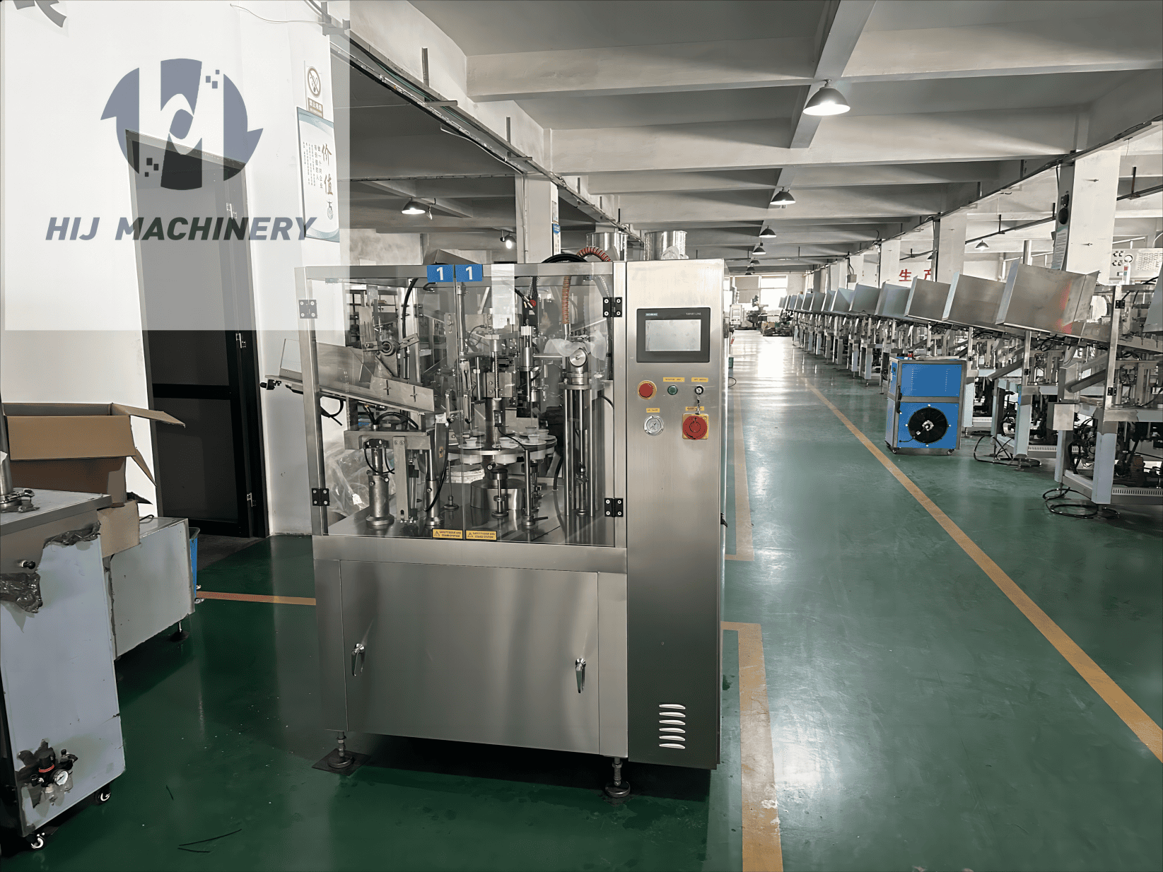
Begin with the actual configured machine rather than an outline copied from a catalogue. The TF-60 document describes a plastic and composite-tube filling and hot-air sealing platform. Its published dimensions are 1950 × 1000 × 1800 mm, with an approximate machine weight of 850 kg. Optional product-supply and hopper equipment may change the installation arrangement.
The cosmetic tube filling and sealing machine page covers equipment selection and quotation. Here the decision is narrower: whether the selected configuration can be delivered, operated and serviced in your proposed space.
| Planning item | Documented reference | How to use it |
|---|---|---|
| Main-machine footprint | About 2 m² | Equipment occupancy, not an operator or maintenance allowance. |
| Main-machine working area | About 12 m² | A planning reference to reconcile with door opening, loading, access and the approved arrangement. |
| Chiller footprint | About 1 m² | Space occupied by the auxiliary unit, separate from the main-machine outline. |
| Chiller working area | About 2 m² | Check ventilation, hose routing, connections and service access with the selected unit. |
About 12 m²
Review operator position, guard opening, loading, cleaning and removal paths around the equipment.
About 2 m²
Review ventilation, connections and service access for the chosen chiller.
Upstream: empty tubes and prepared product → filler/sealer → downstream: accepted tubes, collection or cartoning
Forester’s My Insight
1.95 m × 1.00 m = 1.95 m²
The dimensional footprint agrees with the document’s approximate 2 m² figure. But the stated working area is about 12 m²—roughly six times that footprint. That comparison explains why choosing a room by machine width and length alone can miss the space needed to operate it.
Adding the two stated working areas gives 12 + 2 = 14 m² as an initial, unadjusted planning subtotal. It is not a minimum room-size guarantee: confirm what each area includes, whether any access space can be shared, and what conveyors, storage and circulation add. This is a calculation from reference data, not a measured customer installation.
Mark the machine’s service side, operator side and tube-loading position on a scaled plan. Show the open-guard envelope and the path for withdrawing a hopper, pump assembly or format parts. Do not substitute a generic clearance number for these checks. A clear aisle on a drawing is not useful if a trolley or product container routinely occupies it.
Place the chiller without blocking the production flow
Decide the chiller location with the equipment supplier. The reference package lists a chiller and its space requirements, but it does not establish remote-placement limits, hose lengths or the final ventilation clearance. Ask for the selected chiller’s installation sheet and the machine cooling-circuit requirements together.
Compare possible positions against hose protection, access to connections, cleaning access and the chiller’s specified air path. If the unit rejects heat into the room, include that load in the room review. Do not assume a process-water drain or building chilled-water connection is required simply because the machine uses a water chiller; confirm the actual circuit, fill, drain and service arrangement.
Draw the material routes before fixing auxiliary positions
Show where operators bring empty tubes, replenish product and collect sealed tubes. Keep rejected packs identifiable and separate from accepted output. If tubes discharge toward a tube cartoning machine, define transfer height, orientation, acceptable seal temperature at transfer and the handoff responsibility. A cartoner is not included merely because the filler has an automatic discharge station.
For a wider manufacturing project, the sunscreen production-line overview addresses the upstream and downstream process. Keep this equipment installation plan connected to that broader material-flow review without treating the filler’s working-area figure as the area of the whole factory.
Specify compressed air at the machine connection
The TF-60 reference document lists a working pressure of 0.5–0.7 MPa and compressed-air consumption of 1.1 m³/min. Record both in the utility schedule. A pressure value without a flow basis is not enough to size the supply.
Unit conversion: 1.1 m³/min × 60 = 66 m³/h. This changes only the time unit; it does not establish free-air delivery, normal-volume conditions, duty cycle or compressor size.
Ask whether the quoted flow is referenced to inlet/free-air conditions or another stated basis, and whether it represents average, maximum or design demand. Have the supplier specify air-quality requirements, the connection size, permitted pressure variation and the proposed local isolation and treatment arrangement.
Review the site with other air users operating. The compressor rating alone does not establish the pressure and flow available after distribution losses. Before production acceptance, verify the specified conditions at the machine inlet during representative machine operation. Use the approved procedure; do not adjust interlocks or reduce protection settings to hide a supply problem.
Build an electrical schedule from the fitted configuration
The document lists 50 Hz, 380 V/220 V, three-phase power. Treat those as configuration choices to be resolved in the order, not proof that every machine can be connected to either supply without modification. The source also says different voltage arrangements may require a transformer.
| Component | Listed power | Scope note |
|---|---|---|
| Main motor | 1.1 kW | Main-drive entry in the reference document. |
| Hot-air generator | 3 kW | Heating-system entry; confirm the fitted sealing configuration. |
| Water chiller | 1.9 kW | Confirm whether it has a separate electrical supply. |
| Jacket-barrel heating | 2 kW | Optional equipment, not assumed in the base supply. |
| Jacket-barrel blending | 0.18 kW | Optional equipment; confirm the product-handling configuration. |
The first three listed entries add to 6.0 kW. Including both listed hopper options makes the arithmetic subtotal 8.18 kW. Neither figure replaces the manufacturer’s final connected-load schedule: controls, other auxiliaries, starting conditions and simultaneous operation still need confirmation.
Obtain the final voltage, phase, frequency, rated current, earthing and protective-device requirements for each connection. A qualified electrical designer should use the approved equipment documentation and site conditions to specify installation. Do not choose cable or breaker size by dividing these partial kW subtotals by voltage.
Check delivery access and the working configuration before arrival
The machine’s published operating dimensions are not its shipping-crate dimensions. Request the actual packed size, handling instructions, lifting points and shipping weight. Walk the delivery route through unloading, doors, lifts and turns before committing to the final position.
The approximate 850 kg machine weight is a starting input for the site review, not a floor-loading calculation. The support arrangement, load concentration, handling equipment and building conditions need assessment. Optional tanks, stored product and auxiliary units must be included where relevant.
Freeze one arrangement drawing and one utility schedule
The approved package should show the equipment configuration, material routes, operator access, service envelopes, connection locations and the responsibility for every interface. Record who supplies the chiller connections, compressor-side equipment, product transfer, discharge conveyor and any cartoner interface. This makes quotation comparisons more useful than comparing machine price alone.
Commission the installed system, not just the empty machine
Check connection identification and utility conditions against the approved schedule. Then demonstrate representative loading, replenishment, format change, cleaning access, discharge and controlled stop/restart using agreed procedures. Confirm that access remains practical with the actual containers, hoses and trolleys in place.
For tube filling automation, sustained accepted output matters more than an unloaded cycle rate. The reference document’s 30–50/min operating-speed entry is not proof of finished-pack throughput for every formulation, tube and seal. Agree the product, format, operating conditions and acceptance criteria for the installation test, and record unresolved items before routine production.
Installation questions to resolve in the quotation
How much floor space does a TF-60 tube filling machine need?
The reference document lists a main-machine footprint of about 2 m² and a main-machine working area of about 12 m². It separately lists about 1 m² of chiller footprint and 2 m² of chiller working area. Use these as planning inputs, then obtain an approved arrangement drawing for the actual configuration and room.
Can the water chiller be placed outside the filling room?
That requires supplier confirmation. Check the approved hose length and route, cooling-water flow and pressure, temperature control, ventilation, service access and any separation requirements. The reference area figures do not establish an allowable remote chiller location.
Is 6 kW the complete electrical supply requirement?
No. It is the arithmetic sum of the listed 1.1 kW main motor, 3 kW hot-air generator and 1.9 kW chiller. It is not a verified complete connected load or a basis for selecting a breaker or cable. Obtain the final electrical schedule, including fitted options, starting conditions and protection requirements.
Does a 1.1 m³/min compressor automatically meet the air requirement?
No. The document lists consumption of 1.1 m³/min and a working-pressure range of 0.5–0.7 MPa, but does not establish the flow-reference conditions or your site's distribution losses and other users. Have the machine supplier and air-system provider confirm the required delivery conditions at the connection point.
Review the proposed space with the equipment configuration
Send your room plan with door sizes, the intended tube and fill volume, the target output, and the available electrical and compressed-air supplies. Include the planned product-feed and discharge equipment so the layout review covers the actual installation scope.
Start from the TF-60 configuration enquiry; pricing and installation interfaces are confirmed for the selected scope.
Discuss My Tube Filling Line LayoutReference and calculation basis
TF-60 automatic plastic tube filling and sealing machine technical package: dimensions, equipment/working areas, weight, utility entries and optional hopper equipment. These are reference-configuration values, not a certified construction design. Historical quotation prices and delivery terms are not current offers.
Area and utility calculations in this guide use the stated figures and show their limits. Confirm the final arrangement, utility schedule and operating requirements with the equipment supplier and your site engineering team.