Every sales brochure lists the same four stations: forming, filling, sealing, punching. What they skip is the fifth variable — the 1.5–3 second index stroke that connects them all. I’ve watched that number destroy multi-vendor blister lines. Index timing drift of 0.8 mm is enough to trigger a cGMP deviation. This guide covers what actually happens inside a capsule blister packing machine, station by station, with the failure modes nobody prints on a spec sheet.
A capsule blister packing machine works by thermoforming PVC or Alu-Alu film into cavities, loading individual capsules into each pocket, heat-sealing aluminum lidding foil at 150–200 °C under 0.3–0.6 MPa pressure, then die-cutting finished blister cards — all driven by a servo-indexed transport system that advances the web 1.5–3 seconds per cycle.
What Is the Overall Process Sequence of a Capsule Blister Packing Machine?
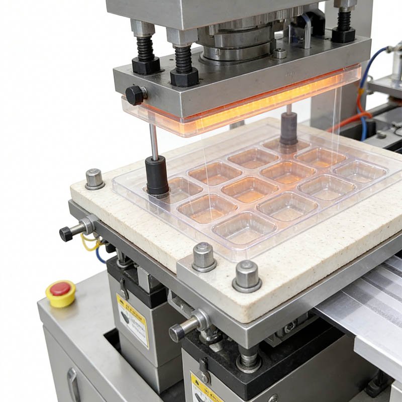
A capsule blister packing machine runs a continuous five-stage sequence: film unwind → thermoform cavities → fill capsules → heat-seal lidding foil → die-cut cards. The entire web advances as one synchronized unit; if any single station lags by more than ±0.1 mm, the downstream cavity-to-die alignment breaks, and every blister card after that point is a deviation.
The machine begins with two film rolls loaded onto a dual-spool holder — a forming film (PVC, PVDC, or cold-form Alu-Alu) at the bottom and a lidding foil (aluminum, typically 20–25 μm) at the top. The forming film feeds forward under servo-controlled tension. From that point, every event happens on a fixed stroke rhythm, measured in cycles per minute.
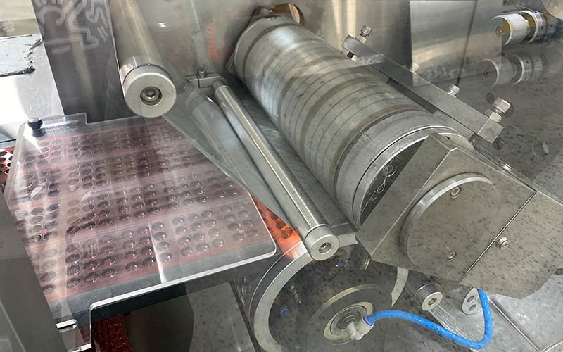
The forming film passes first through a pre-heating zone, then enters the forming station where heated plates soften the film to a thermoformable state. A punch-and-die tool, matched exactly to your capsule size, presses cavities into the film. The web then steps forward into the filling zone. Capsules drop by gravity, brush, or vibration into the open pockets. The filled web then advances under the sealing station, where a heated roller or plate bonds the lidding foil. The sealed web moves one final step to the punching station, where a die cuts individual blister cards.
That sequence sounds straightforward. It isn’t. The challenge is synchronization. Each station operates on the same index stroke — the precise distance the film advances per cycle. If a PLC controlling the forming motor and a separate PLC controlling the sealing motor use different index reference points, the accumulated error compounds. That’s the multi-vendor synchronization problem I’ll return to later.
How Does the Forming Station Create Capsule Blister Cavities?
The forming station softens PVC or PVDC film to 120–160 °C, then uses compressed air at 4–6 bar or a mechanical plug to push the film into a precisely machined aluminum mold — creating cavities sized to ±0.05 mm tolerance for the specific capsule body diameter and length.
The forming film — typically 250 μm PVC, though thicker PVDC laminate or Alu-Alu cold-form foil is used for moisture-sensitive APIs — feeds from the bottom spool. A heating plate above and below the film raises the material to its thermoforming window. Too cold, the film tears or fails to conform. Too hot, the wall thickness thins unevenly, leaving cavities with sub-specification barrier performance.
Once softened, compressed air (or a mechanical plug assist for deeper draws) pushes the film into the mold tooling. The mold pocket dimensions are matched to your specific capsule size — size 00, 0, 1, 2, 3, or 4 — with typical cavity-to-capsule clearance of 0.3–0.5 mm on each side. Tighter than that, and capsules jam. Looser, and the capsule rattles, risking damage to printed surfaces and patient perception issues downstream.
The mold itself is the most expensive consumable on the line. A standard set costs $1,200–$4,500 depending on complexity and material. For a machine handling four capsule sizes, that’s a tooling inventory decision, not just a technical one. Quick-change mold systems — those that swap in under 20 minutes without tools — are worth the premium if your SKU count exceeds three formats.
PVC film requires 120–140 °C; PVDC laminate needs 140–160 °C. Temperature uniformity across the heating plate must be ±2 °C or wall thickness variation exceeds 8%, degrading cavity barrier performance.
Compressed air at 4–6 bar (or plug-assist for draw ratios above 1:1.5) pushes softened film into the mold cavity. Cavity depth for standard capsule sizes is 18–22 mm. The film must conform within 0.3 seconds or surface blemishing occurs.
Mold tooling is CNC-machined aluminum or hardened steel. Cavity-to-capsule clearance of 0.3–0.5 mm prevents jamming while maintaining stable positioning for the sealing step. Mold sets for a single capsule size run $1,200–$4,500.
How Does the Capsule Filling Station Place Capsules Into Blister Cavities?
The filling station uses one of three mechanisms — gravity brush, vibrating feeder, or vacuum suction — to orient and drop capsules into formed cavities. Orientation accuracy (seam-up versus seam-down) matters for visual inspection systems; a well-tuned brush feeder achieves 99.7–99.9% fill rates with defect rates below 0.1% at speeds up to 400 cycles per minute.
Capsules are harder to fill reliably than tablets. A tablet is a solid disc — it has one stable resting orientation. A capsule is a cylinder with a dome cap and a body. Drop it the wrong way and it sits above the cavity rim, preventing the lidding foil from sealing flush. That single misoriented capsule can seal improperly across its entire row.
Three feeding mechanisms dominate the market. The brush feeder is the most common on mid-range machines running up to 200 cycles/minute: rotating brushes sweep capsules across the formed web, and capsules fall by gravity into open cavities. The vibrating track feeder improves orientation control and handles soft-gel capsules better than brushes — vibration amplitude and frequency are tuned to each capsule weight and geometry. For high-speed lines above 300 cycles/minute or for high-value APIs, vacuum suction nozzles pick individual capsules from an orientation bowl and place them precisely, achieving fill accuracies above 99.9%.
Missing capsule detection happens at this stage. A photoelectric sensor or camera-based vision system scans each cavity row as the web exits the filler. An empty cavity — or a partially inserted capsule — triggers a signal that either stops the machine or flags that card position for downstream rejection. WHO TRS 992 Annex 3 requires that empty-pocket detection systems be validated as part of the filling station qualification.
I ran a commissioning in a plant outside Dhaka in 2021. The client was running size 0 HPMC vegetarian capsules — slightly longer than standard gelatin, lighter by 12%. The brush feeder parameters had been copied directly from their previous gelatin capsule line. Fill rate on Day 1: 94.3%. The reject bin was full by the second shift. We spent four hours adjusting brush rotation speed and adding a slight negative-pressure assist at the filling zone. By Day 3, fill rate was 99.6%. Nobody had told the operator that HPMC capsules need a different brush speed setting. That conversation is now in every FAT protocol I write.
What Happens at the Heat Sealing Station — and Why Does Temperature Precision Matter?
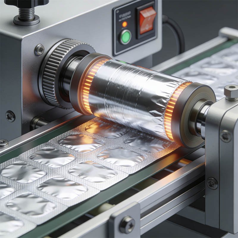
The sealing station bonds aluminum lidding foil to the formed film web using heat at 150–200 °C and pressure at 0.3–0.6 MPa for a dwell time of 0.3–1.0 second — creating a hermetic seal validated by ASTM F2338 dye-ingress or USP <1207> helium leak testing. A ±5 °C temperature deviation from the validated setpoint is sufficient to cause either cold seals (delamination) or hot seals (peel-seal failure on patient opening).
The sealing station is where the blister goes from open container to sealed drug product. That transition is a regulatory boundary. Before sealing: the product is exposed product. After sealing: it’s a finished packaged drug. The sealing validation data you generate here goes into your dossier. If you change the sealing temperature by more than 5 °C from your validated setpoint, you’re in change-control territory in most regulated markets.
The lidding foil advances from the top spool and is pressed onto the formed film web by a heated sealing plate. The sealing layer — a heat-seal lacquer on the foil underside — activates at temperature and bonds to the PVC forming film surface. Sealing pressure distributes across the web surface area, which means the mold support plate beneath must be perfectly flat. A 0.02 mm bow in the support plate creates a pressure differential that generates a cold-seal line running across all cavities in that row.
Dwell time is the third variable. Standard dwell for PVC–Alu is 0.4–0.6 seconds. Cold-form Alu-Alu sealing runs slower — typically 0.8–1.2 seconds — because the forming material itself conducts heat differently. Reducing dwell time to increase output without re-validating the seal strength is one of the most common unreported production shortcuts I’ve seen across emerging market facilities.
Container closure integrity at the sealing station is governed by USP <1207> and ASTM F2338 (dye-ingress at 60 mbar for blister packs). EU GMP Annex 1 (2022 revision) requires that sealing process parameters — temperature, pressure, and dwell time — be documented, monitored continuously, and included in the batch record. A validated sealing window must be established during IQ/OQ/PQ before commercial manufacture begins.
How Does the Punching Station Die-Cut Individual Blister Cards?
The punching station uses a hardened steel die set to cut individual blister cards from the sealed web in a single downstroke — producing cards to ±0.3 mm dimensional tolerance. Card geometry, cavity layout, and rounded corners are all defined by the die tooling, which must be aligned to within ±0.1 mm of the formed cavity center or the card edge encroaches on cavity sealing area, compromising seal integrity.
The punching station is the last station and the most mechanically violent. A hardened steel upper die descends at high speed onto a lower die matrix, cutting through the sealed web in a single stroke. The cut must be clean — no tearing, no edge burrs — because any burr on the card edge is a patient handling issue and, in some markets, a regulatory non-conformance.
Card size and cavity layout are fixed at the die design stage. Standard cards for a 10-capsule strip (2×5 layout) measure approximately 57 mm × 85 mm. Custom cavity grids — 3×4, 4×4, or irregular layouts — require custom die sets. Each die set costs $800–$2,500 and has a service life of 2–5 million cycles before edge wear requires re-grinding or replacement.
After punching, finished cards drop by gravity onto a conveyor or collection tray. Waste film — the web skeleton remaining after cards are cut — is wound onto a waste take-up reel. That waste reel must be accounted for in material balance calculations. A missing waste reel record is a GMP documentation gap I’ve seen cited in three CDSCO inspection reports in the past five years.
How Does Index Timing Synchronize All Four Stations Simultaneously?
Index timing is the master heartbeat of a capsule blister packing machine: a servo motor advances the film web one precise stroke length every 1.5–3 seconds, and all four station operations — form, fill, seal, punch — execute in parallel during that single stroke. Any drift in index stroke length, even 0.5 mm, accumulates across 50+ strokes into cavity misalignment at the punching station.
This is the mechanism most buyers never ask about. The forming station creates cavities at position X. The web advances one stroke to position X‑plus‑one‑pitch. The filling station fills cavities at position X‑plus‑one‑pitch. The web advances again. The sealing station seals at position X‑plus‑two‑pitch. One more advance. The punching die cuts at position X‑plus‑three‑pitch. For this to work, the index pitch must be identical at every stroke — not approximately identical. Exactly identical.
On a single-architecture machine — one PLC, one servo system — index pitch repeatability is controlled by the servo encoder. HIJ’s DPP‑260 uses a Siemens or Allen-Bradley servo with encoder resolution of 10,000 pulses per revolution, delivering index repeatability of ±0.05 mm. That number matters because the punching die requires cavity centers within ±0.1 mm.
On a multi-vendor line — a German forming unit connected to a Chinese sealing station with a locally sourced PLC integration — the two PLCs may use different reference clocking. Temperature-related thermal expansion of the film web over an 8-hour shift introduces additional drift. I’ve seen multi-vendor configurations where cumulative index error after 4 hours of production reached 1.2 mm. That triggered 11 consecutive cards with punching-die encroachment on the cavity sealing area. Eleven cards per cycle, every cycle, for two hours, before anyone caught it.
The index stroke is not a mechanical parameter. It’s a pharmaceutical parameter. A 0.8 mm drift in index timing at the punching station translates directly to seal-area encroachment — the same defect that shows up as a container closure integrity failure in your stability samples 12 months later. Demand a single-architecture control system. Demand a full-line FAT before shipment. — Forester Xiang, HIJ Machinery
What Are the Key Technical Specifications of a Capsule Blister Packing Machine?
A pharmaceutical-grade automatic capsule blister packing machine typically runs 80–500 blisters per minute, handles forming film widths of 110–300 mm, operates on PVC/PVDC/Alu-Alu forming film, requires a 3–7 kW power supply, and occupies a footprint of 1.5–4.5 m in length — with GMP-compliant 304 stainless steel and 316L contact-part construction standard on pharmaceutical models.
| Parameter | Entry-Level (DPP-250 Class) | Mid-Range (DPP-260 Class) | High-Speed Line |
|---|---|---|---|
| Output Speed | 80–150 blisters/min | 150–300 blisters/min | 300–500+ blisters/min |
| Forming Film Width | 110–150 mm | 150–260 mm | 260–320 mm |
| Forming Film Materials | PVC | PVC, PVDC, Alu-Alu | PVC, PVDC, Alu-Alu, PET |
| Sealing Temp Range | 150–180 °C | 150–200 °C | 150–220 °C |
| Index Repeatability | ±0.2 mm | ±0.05–0.1 mm | ±0.05 mm |
| Control Architecture | Single PLC, relay logic | Siemens / Allen-Bradley PLC + servo | Multi-axis servo, vision integration |
| Empty Pocket Detection | Optional photoelectric | Standard photoelectric / camera | High-speed camera + AI reject |
| GMP Contact Surface | 304 SS (standard) | 304 SS / 316L product-contact | 316L full contact surfaces |
| Machine Footprint (L) | 1.5–2.2 m | 2.5–3.5 m | 4.0–6.0 m |
| Power Requirement | 3–4 kW | 4–6 kW | 6–12 kW |
In my 20 years of commissioning blister lines across facilities in Southeast Asia and Latin America, I’ve watched plant managers obsess over forming temperature specs on paper, only to discover on Day 1 of production that their multi-vendor line — a German forming unit paired with a Chinese sealing station — couldn’t synchronize index timing. The result? Blister cavities misaligned by 0.8 mm, triggering a full cGMP deviation report and a three-week production halt. Nobody in the sales brochure warns you that inter-machine PLC protocol conflicts are the silent killer of blister line efficiency.
Before signing any equipment contract, demand a full FAT (Factory Acceptance Test) that runs the entire forming-to-punching sequence as one integrated system — not station by station. At HIJ, our turnkey blister solutions are engineered on a unified control architecture precisely to eliminate this multi-vendor synchronization risk from day one.

How Do Servo Motors and PLC Architecture Control a Capsule Blister Machine?
A GMP-grade capsule blister packing machine uses a servo motor with encoder-based position feedback to drive the film transport system, with a programmable logic controller (PLC) coordinating station timing, sealing temperature, and detection signals on a single unified bus — eliminating the inter-PLC synchronization latency that causes index drift in multi-vendor configurations.
The control architecture is what separates a pharmaceutical-grade machine from an industrial one. On a PLC-servo system, the servo motor receives position commands from the PLC in real time. Encoder feedback confirms actual shaft position. The difference between commanded and actual position — the following error — is monitored continuously. On Siemens S7-based systems, following error alarms trigger within 5 ms. That response speed is why single-architecture machines can hold ±0.05 mm index repeatability across an 8-hour production shift.
The HMI (human-machine interface) on a modern capsule blister machine stores recipe parameters for each product format: forming temperature, sealing temperature, dwell time, index speed, and filling station parameters. A validated recipe prevents operator-introduced parameter drift — a 21 CFR Part 11 requirement if the facility is targeting US market registration. Electronic batch records generated by the PLC system capture all process parameters at every cycle, timestamped and tamper-evident.
One detail most buyers overlook: the servo drive’s thermal management. A servo running at sustained high speed in a 30 °C cleanroom generates significant heat. Without active cooling or proper cabinet ventilation, drive temperature can rise to 65–70 °C — reducing MTBF and, more immediately, introducing thermal drift in encoder readings. I’ve seen two servo drive failures in Indian plants directly attributable to insufficient drive cabinet cooling. Both plants were in states with summer ambient temperatures above 38 °C.
How Does a Capsule Blister Packing Machine Adapt to Different Capsule Sizes and Formats?
Capsule size changeover on a blister packing machine requires replacing four components: the forming mold, the filling guide plate, the punching die, and the feeder brush or track. On a quick-change tooling system, this changeover completes in 15–25 minutes; on a conventional bolted-down tooling system, it takes 60–90 minutes and requires post-change verification of cavity alignment before production can restart.
The pharmaceutical capsule size range runs from size 5 (smallest, 0.13 mL fill volume) to size 000 (largest, 1.37 mL). Each size has a different body diameter and length, requiring its own mold cavity geometry. A machine configured for size 0 capsules cannot run size 1 capsules without a forming mold change — the cavity dimensions are fixed in the mold tooling.
Quick-change mold systems are the key to multi-format productivity. The mold plate locks to the forming station with a quarter-turn cam mechanism and a precision locating pin. Changeover time drops from 70 minutes to 18 minutes. For a plant running 4 SKUs across 2 capsule sizes, that 52-minute saving per changeover translates to 4–6 additional production batches per month. That number is worth calculating before buying the cheaper machine with conventional tooling.
Soft-gel capsules add another variable. Soft-gels are pliable — they deform under brush feeder pressure and can stick together at elevated cleanroom temperatures. Lines intended for soft-gel capsules need chilled filling zone air (typically 18–20 °C), gentler vibration feeders, and slightly larger cavity clearances (0.5–0.8 mm versus 0.3–0.5 mm for hard-shell capsules). If your product mix includes soft-gels, specify this upfront — it affects the forming station cooling system and the cavity geometry spec.
- Forming mold: Unique per capsule size — defines cavity length (typically 18–24 mm), diameter (5.8–9.9 mm depending on size), and draw depth. CNC-machined aluminum, $1,200–$4,500 per set.
- Filling guide plate: Aligns capsule orientation at the filling station. Must match capsule diameter to prevent misorientation. Changed with every capsule size switch.
- Punching die set: Defines card dimensions and cavity layout (e.g., 2×5 for 10-capsule cards). Must align with forming mold pitch to within ±0.1 mm.
- Brush or feeder track: Brush width and track geometry tuned to capsule diameter. Soft-gel configurations require lower-force vibration tracks and chilled air assist.
- Recipe parameters: PLC recipe — forming temperature, dwell time, index speed, sealing temperature — validated per capsule format and stored as locked parameters requiring supervisor authorization to change.
What GMP Requirements Apply to How a Capsule Blister Packing Machine Operates?
Under WHO TRS 992 Annex 3 and EU GMP Annex 15, a capsule blister packing machine must complete IQ/OQ/PQ validation before commercial use — with process parameters (sealing temperature ±5 °C, forming temperature ±3 °C, index repeatability ±0.1 mm) documented in the OQ, and container closure integrity confirmed by ASTM F2338 or USP <1207> testing during PQ.
The CDSCO reviewer cited ICH Q1A(R2) directly during a 2022 dossier review for a client targeting the Indian market. The question was whether Zone IVb stability data existed for the specific blister format proposed. The dossier had been prepared based on Zone II data from a European manufacturing site. The reviewer asked why Zone IVb extrapolation was absent. The dossier went back for 8 months of additional stability work. The machine specification — and particularly the sealing station validated parameters — had to be re-documented for Zone IVb conditions.
Machine qualification isn’t bureaucracy. It’s the operational record that proves your forming temperature, your sealing pressure, and your index speed were all within validated limits during every production batch. For emerging market plants targeting WHO prequalification or US FDA registration, the IQ/OQ/PQ documentation package is often the single largest pre-inspection risk factor — not the machine itself.
See our detailed guide on IQ/OQ/PQ validation for capsule blister packaging machines for a full protocol framework.
Is a Capsule Blister Packing Machine Different from a Tablet Blister Packing Machine?
Capsule and tablet blister packing machines share the same four-station architecture, but differ in three operational areas: cavity geometry (capsules need deeper, cylindrical cavities; tablets use shallower, disc-shaped pockets), filling mechanism (capsules require orientation-controlled feeders; tablets can use simpler gravity hoppers), and forming film thickness (capsule cavities require deeper draws, typically demanding 250–300 μm PVC versus 200–250 μm for tablets).
The core process is the same. The mechanical differences are in the tooling and feeder configuration. A machine designed primarily for tablets can often run capsules with a mold and feeder change — but verify the forming station draw depth capability first. Some entry-level tablet blister machines have maximum cavity depths of 8–10 mm, which won’t accommodate size 00 or 000 capsules (cavity depth required: 20–24 mm).
Our tablet blister packing machine page covers the tablet-specific configuration in detail — including the flat-die forming system optimized for disc-geometry products.
Frequently Asked Questions: How a Capsule Blister Packing Machine Works
A standard automatic capsule blister packing machine completes one index cycle in 1.5–3 seconds, producing 80–500 finished blister cards per minute depending on the number of cavities per card and machine speed class.
The heat-seal lacquer on aluminum lidding foil activates within a narrow temperature window. Below the setpoint by more than 5 °C, the lacquer doesn’t fully activate, producing cold seals that delaminate under standard packaging handling or fail container closure integrity (CCI) testing per ASTM F2338. Above the setpoint by more than 5 °C, the lacquer over-bonds to the forming film surface, increasing peel force beyond patient-safe limits — particularly relevant for elderly or pediatric users who cannot exert sufficient force to push tablets out.
Yes, but the configuration requires modification. Soft-gel capsules need a chilled filling zone (18–20 °C air supply), a lower-force vibration feeder, and larger cavity clearances (0.5–0.8 mm versus 0.3–0.5 mm for hard-shell). Specify multi-format capability upfront — retrofitting soft-gel handling on a hard-shell-only machine typically costs $8,000–$18,000 in modification work and re-validation.
Industry standard uses “blisters per minute” to mean blister cards per minute, not individual cavities. A machine rated at 200 blisters/min producing a 10-cavity card is filling 2,000 capsules per minute.
Empty-pocket detection uses a photoelectric sensor or camera system to confirm every cavity contains a capsule before the web advances to sealing. WHO TRS 992 Annex 3 requires that filling station detection systems be validated during OQ. It is a GMP requirement for pharmaceutical use, not an optional feature. Missing a single empty pocket in a sealed blister is a patient safety event — and a potential recall trigger.
A standard IQ/OQ/PQ validation protocol for a single-product, single-format capsule blister packing machine takes 4–8 weeks from machine installation to PQ completion, assuming the URS was prepared correctly and no deviation occurred during OQ runs. Multi-product, multi-format qualifications take 10–16 weeks. Add 6–8 weeks if regulatory dossier submission requires Zone IVb stability data from the blister format.
Thermoforming uses heat (120–160 °C) to soften PVC or PVDC film before pressing into a mold — the standard process for most capsule blister applications, producing blisters with moisture vapor transmission rates (MVTR) of 2–6 g/m²/day (PVC) or 0.1–0.5 g/m²/day (PVDC).
Cold forming (Alu-Alu) uses aluminum foil laminate that is physically deformed into a cavity by a mechanical punch at room temperature — no heat required. The result is MVTR of 0.02–0.5 g/m²/day, roughly 10–300 times lower than PVC, making it the required choice for highly moisture-sensitive APIs. Cold forming is slower (typically 20–30% fewer cycles per minute than thermoforming) and requires higher forming forces, meaning the machine structure must be rated for cold-form duty — not all blister machines are.
A Factory Acceptance Test (FAT) is a performance verification run at the manufacturer’s facility before shipment. A station-by-station FAT confirms each module works individually — it does not test inter-station synchronization. A full-line FAT runs the complete forming-filling-sealing-punching sequence continuously for 2–4 hours at rated speed, confirming index timing synchronization, detecting PLC communication latency, and generating the first batch of production-grade blister cards for dimensional verification. For multi-vendor lines, a full-line FAT is the only way to detect inter-PLC synchronization failures before they cause a cGMP deviation on your production floor.
Continue Learning: Related Guides in This Series
If you’re building a complete understanding of capsule blister packaging, these resources go deeper into the areas this guide introduced:
- What Is Capsule Blister Packaging? — A beginner’s guide to the fundamentals: what blister packaging is, why it dominates pharmaceutical markets, and how to read a blister card specification.
- How to Choose the Right Capsule Blister Packing Machine — A buying guide covering output requirements, forming film choice, tooling cost, and the questions to ask every supplier before signing a contract.
- HIJ Capsule Blister Packing Machine — DPP-260 Specifications — Full technical specifications, cavity format options, and inquiry form for the HIJ DPP-260 automatic capsule blister packing machine.
20 years of field commissioning across Southeast Asia, Latin America, and the Middle East. We don’t just sell machines — we specify the right forming station depth, servo architecture, and FAT protocol for your capsule format, output target, and regulatory market. Tell us your capsule size, annual volume, and target market. We’ll send a line configuration proposal within 48 hours.